Choosing an LED strip is easy. Specifying an LED strip system that still performs correctly after installation is much harder.
A complete LED strip specification must define more than voltage, wattage and color temperature. It should connect the required lighting effect with the strip, aluminum profile, diffuser, driver, controller, cable, feed method, operating environment and acceptance tests.
Use this LED Strip Specification Builder to create four coordinated project documents:
- A project design brief
- An LED strip product specification
- A system integration schedule
- A validation and submittal schedule
That distinction matters. A strip can meet every value on its datasheet and still produce visible dots, inconsistent color, excessive voltage drop, flicker, overheating or premature outdoor failure after it is installed.
Quick Answer: What Should an LED Strip Specification Include?
At minimum, a professional LED strip specification should define:
- Application and visual intent
- Installed light output target
- CCT, color tolerance and color-quality requirements
- Operating voltage and circuit layout
- Power consumption and driver sizing basis
- Maximum electrical run per feed
- PCB width, cut length and mechanical restrictions
- Aluminum profile and diffuser
- Indoor, damp, wet or chemically exposed conditions
- Dimming and control protocol
- Operating temperature and thermal requirements
- Required certifications and destination market
- Sample, test report and production acceptance requirements
- Cable, connector, reel, labeling and packaging details
Do not begin by asking, “Which LED strip should I buy?”
Begin with four better questions:
- What must the finished installation achieve?
- What physical and electrical limits cannot change?
- Which performance values must be measured?
- What evidence must the supplier provide?
A Product Specification Is Not a System Specification
An LED strip is only one component of the finished lighting system.
The installed result may also depend on:
- Aluminum profile depth and width
- Diffuser material and transmission
- Distance between the LEDs and diffuser
- Mounting surface and heat dissipation
- Driver output quality
- Dimmer or controller compatibility
- Cable length and conductor size
- Number and location of power feeds
- Ambient temperature
- Waterproof encapsulation
- Field joints and cable entries
For example, a strip may deliver 1,200 lumens per meter when measured alone. After installation behind a diffuser, the usable output can be lower. The exact loss depends on the diffuser, profile geometry, optical distribution and test method—not on one universal percentage.
The correct specification therefore separates:
| Specification layer | What it defines |
|---|---|
| Design requirement | The result the project needs |
| LED strip specification | The construction and performance of the strip |
| System specification | Driver, controller, profile, cable and feed arrangement |
| Validation requirement | How compliance will be demonstrated |
Choose Your Specification Mode
A useful builder should not force every user to understand PCB copper weight, chromaticity coordinates or PWM frequency before starting.
Guided Mode
Recommended for:
- Interior designers
- Architects
- Contractors
- Distributors
- Purchasing teams
- Private-label brands
Guided Mode asks practical questions such as:
- Is the light source directly visible?
- How long is each illuminated section?
- Is the installation indoors, outdoors or near water?
- Does the project require smooth dimming?
- Will the same product be reordered later?
The builder then translates those answers into technical requirements.
Engineering Mode
Recommended for:
- Lighting engineers
- OEM product developers
- Control-system integrators
- Project consultants
- Test and compliance teams
Engineering Mode exposes advanced fields including:
- Target lumens per meter
- Maximum circuit current
- Voltage-drop limit
- PCB width and copper construction
- Cut-unit length
- Tc measurement point
- Chromaticity tolerance
- Dimming method and temporal light modulation
- Test standards and certification scope
Both modes should generate the same professional output. The difference is how much technical detail the user enters directly.
Stage 1: Define the Project Before Selecting the Strip
Step 1: Describe the Application
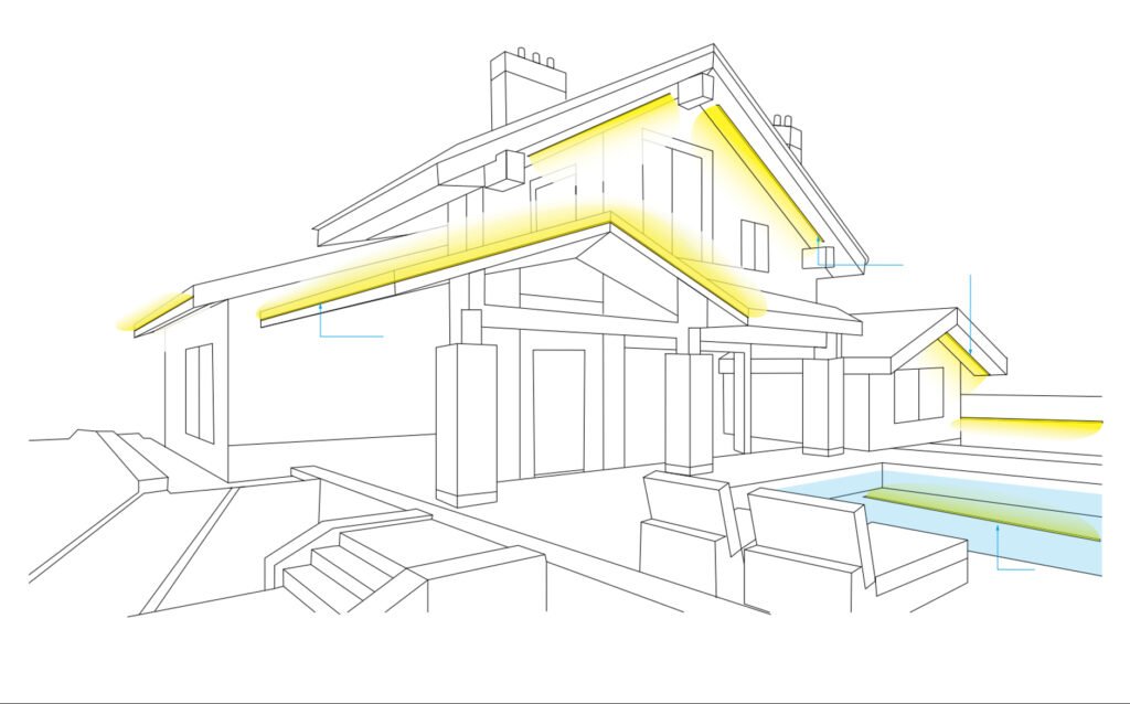
Start with the project, not the LED package.
Select the primary application:
- Cove lighting
- Under-cabinet lighting
- Retail shelving
- Display cabinet
- Hospitality lighting
- Stair or handrail lighting
- Linear architectural lighting
- Backlit stone or translucent material
- Signage
- Outdoor façade
- Landscape lighting
- Marine or coastal installation
- Sauna or high-temperature environment
- Furniture integration
- Machine or equipment lighting
- Custom OEM product
Then define the visual role:
- Decorative accent lighting
- Indirect ambient lighting
- Task lighting
- Product presentation
- Main functional illumination
- Dynamic color effect
- Wayfinding or identification
- Camera or broadcast environment
A strip suitable for an indirect ceiling cove may be unsuitable for a shallow shelf profile, even when both require the same CCT and wattage.
Step 2: Map the Installation Geometry
“Total project length” is not enough to calculate a reliable system.
Record:
- Total illuminated length
- Length of every individual segment
- Number of branches
- Distance from driver to each branch
- Planned feed position
- Location of corners
- Available profile width and depth
- Distance from LEDs to the diffuser
- Viewing distance
- Whether the source is directly visible
- Driver location and maintenance access
The builder should distinguish three different lengths:
Total Project Length
The combined length of all strips in the project. This is useful for estimating quantities and total power.
Continuous Visual Length
The length that should appear as one uninterrupted line of light.
Electrical Run Length
The strip length powered by one feed or circuit.
These values are often different.
A 20-meter architectural line does not necessarily require one 20-meter electrical run. It may be divided into four coordinated 5-meter branches while remaining visually continuous.
This is one of the most important differences between lighting design and LED strip procurement.
Step 3: Define the Required Lighting Effect
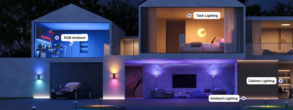
Choose the lighting effect before choosing LED density.
Is the Light Source Visible?
If the strip is directly visible or installed in a shallow profile, the project may require:
- A smaller LED pitch
- A deeper aluminum profile
- A higher-diffusion lens
- A COB or CSP light source
- A higher-density SMD construction
- A greater setback from the diffuser
“Dotless” is a system result, not simply a product label.
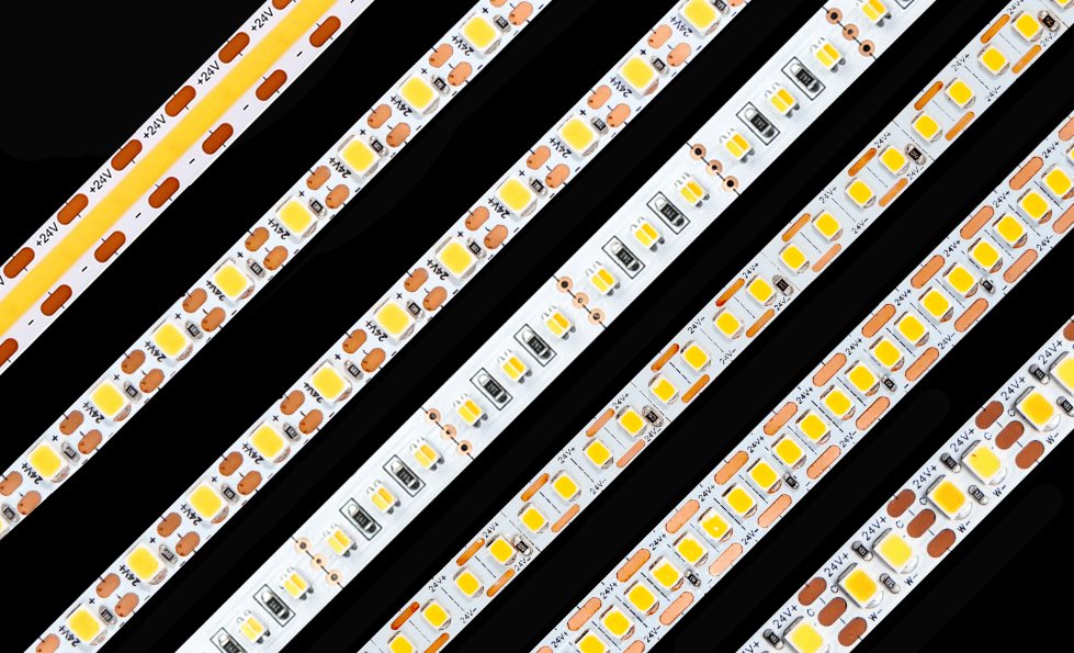
COB strips can create a more continuous luminous surface, but visible segmentation may still appear at low dimming levels, around cut points, through shallow optical systems or in reflective materials. Conversely, a properly selected SMD strip can appear continuous inside a suitable profile.
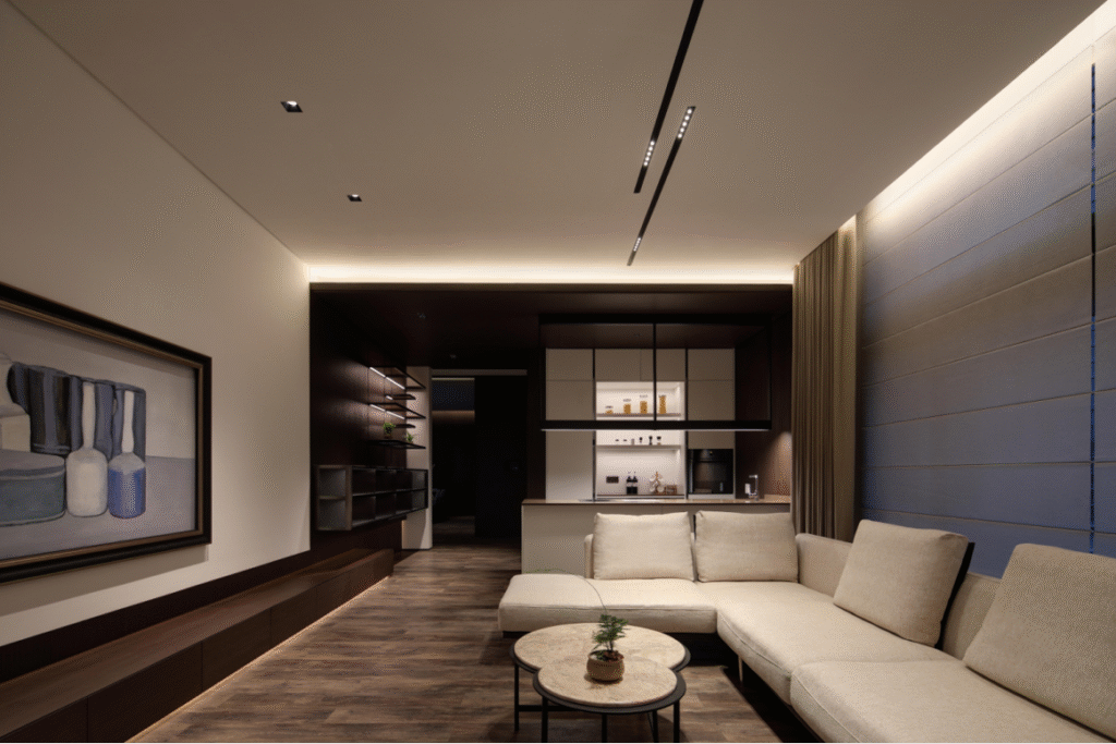
Use the Xmart COB LED strip range when a continuous emitting surface is a priority, but validate the actual strip-profile-diffuser combination with a physical sample.
Direct or Indirect Lighting?
Indirect cove lighting depends heavily on:
- Distance to the reflecting surface
- Surface color and reflectance
- Cove geometry
- Strip orientation
- Beam distribution
- Setback from the cove edge
The brightest strip is not automatically the best choice. Poor placement can create a bright line near the source and weak illumination elsewhere.
Decorative or Functional Output?
For decorative applications, wattage may be a useful product filter. For functional lighting, it is not a sufficient design target.
Prefer one of these requirements:
- Target illuminance at the task plane, in lux
- Minimum installed lumens per meter
- Target luminance of a backlit surface
- Minimum vertical illuminance
- Required uniformity ratio
A statement such as “9.6 W/m LED strip” describes electrical input. It does not guarantee the installed lighting result.
Step 4: Specify Color and Color Quality
Select the Color Mode
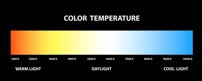
Choose one:
- Fixed white
- Tunable white
- Dim-to-warm
- RGB
- RGBW
- RGBCCT
- Addressable RGB or RGBW
- Single-color non-white
- Custom spectrum
These options require different conductor counts, controllers, wiring arrangements and control strategies. They should not be treated as interchangeable versions of the same strip.
Specify CCT Correctly
For fixed white, define:
- Nominal CCT
- Permitted CCT range
- Initial color tolerance
- Batch-to-batch tolerance
- Repeat-order color requirement
For demanding hospitality, retail or architectural projects, “3000K” alone may be insufficient.
Consider specifying:
- Maximum initial SDCM
- Chromaticity coordinates or an agreed bin
- Acceptable color shift during operation
- Repeat-order binning or approved master sample
SDCM describes proximity to a target chromaticity, but it does not describe spectrum quality or how saturated colors will appear.
CRI Is Not the Whole Color Specification
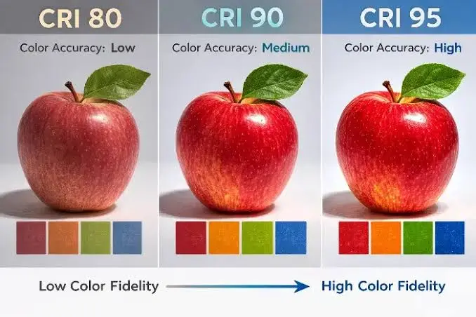
CRI remains widely used, but a single Ra value can conceal meaningful spectral differences.
Depending on the application, specify:
- Minimum CRI Ra
- Minimum R9
- Relevant special color-rendering indexes
- IES TM-30 fidelity requirements
- IES TM-30 gamut requirements
- Specific color-vector preferences
- Spectrum or melanopic requirements where relevant
There is no universally “best” TM-30 result. The appropriate combination depends on whether the design prioritizes fidelity, vividness, preference or a particular material appearance. The Illuminating Engineering Society’s TM-30 guidance explains why color criteria should follow the design intent.
For example:
- Retail food lighting may prioritize the appearance of reds, skin tones or fresh produce.
- Museums may prioritize color fidelity and stability.
- Hospitality projects may accept controlled increases in color saturation.
- Human-centric applications may require spectrum data beyond CRI.
Do not automatically specify CRI 95 for every project. Higher CRI can involve trade-offs in efficacy, price, output and spectrum, while two CRI 95 strips can still render colors differently.
Step 5: Define the Operating Environment
Do not select an IP rating until the real exposure is understood.
Choose all relevant conditions:
- Dry indoor
- Damp or humid
- Splashing water
- Rain
- Temporary immersion
- Continuous immersion
- Condensation
- Direct sunlight
- High UV exposure
- Salt air
- Chlorine
- Cleaning chemicals
- Oils or solvents
- High ambient temperature
- Low-temperature operation
- Frequent thermal cycling
- Enclosed installation
- Food-contact or hygiene-related area
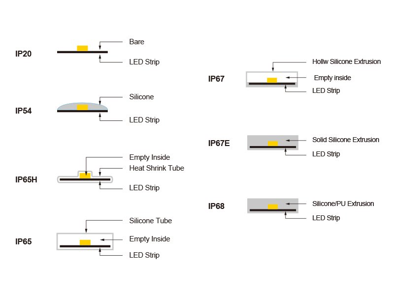
IP ratings classify resistance to solid particles and water under defined test conditions. They do not automatically establish resistance to UV, chlorine, salt, cleaning chemicals, mechanical stress or years of thermal cycling.
An “IP68” label also does not, by itself, prove that a strip system is suitable for a swimming pool. The complete installation must consider:
- Immersion conditions
- Depth and duration
- Encapsulation material
- Chlorine or salt resistance
- Cable entry construction
- Field joints
- Driver location
- Electrical isolation
- Local pool-safety regulations
- Inspection and maintenance access
For outdoor projects, review why LED strips can fail after passing an IP test before finalizing the specification.
Step 6: Record Mechanical Constraints
Specify:
- Maximum PCB width
- Available installation depth
- Minimum cut length
- Required cut locations
- Minimum bending radius
- Permitted bending direction
- Cable exit direction
- Connector clearance
- Profile compatibility
- Mounting method
- Adhesive requirements
- Additional mechanical retention
- Service and replacement method
For millwork, shelves or miniature luminaires, PCB width may be a hard constraint. Xmart can manufacture certain custom strip configurations across a broad range of PCB widths, including specialized ultra-narrow LED strips, but narrow construction increases the importance of current density, thermal management and mechanical handling.
A narrower PCB is not automatically better. It can mean:
- Less copper area
- Higher conductor resistance
- Greater thermal concentration
- Smaller soldering pads
- More difficult installation
- Lower mechanical robustness
The specification should prioritize the real fit requirement without creating unnecessary thermal or electrical risk.
Step 7: Define Controls Before Finalizing the Strip
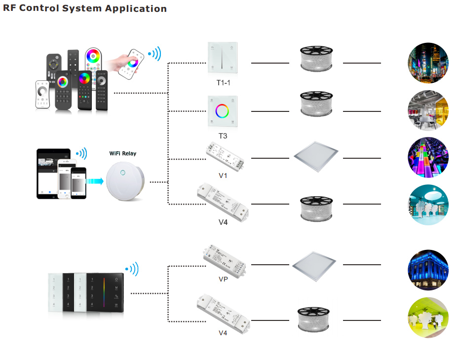
Select the required control method:
- On/off only
- Mains phase dimming
- 0–10V
- DALI
- PWM
- DMX512
- SPI or addressable-pixel control
- Bluetooth
- Zigbee
- Matter ecosystem
- Proprietary building-control system
The strip itself is only one part of the control chain.
For example, a constant-voltage white strip is not inherently “DALI.” DALI functionality is provided by the driver or controller. DALI Device Type 6 generally controls a single output, while Device Type 8 supports color-control functions such as tunable white or RGBWAF. The DALI Alliance device-type guidance and DALI color-control guidance provide the correct terminology.
Similarly, a basic LED strip does not become Matter-certified simply because it is connected to a Matter-compatible controller. Certification and interoperability claims should identify the exact smart component.
For a complete system, coordinate the strip with the LED controller and LED driver rather than specifying each component independently.
Stage 2: Convert the Design Intent Into Engineering Requirements
Step 8: Calculate the Required Installed Output
The builder should separate three values:
- Bare-strip output
- Profile or diffuser output
- Installed project output
A simplified preliminary relationship is:
Estimated installed lumens = bare-strip lumens × optical transmission factor × installation factor
However, optical transmission alone may not predict the final result accurately. Profile geometry, beam distribution, reflections and thermal conditions also affect delivered light.
For critical projects, require one of the following:
- Photometric data for the complete strip-and-profile combination
- An integrating-sphere report for the assembled system
- A project mock-up
- Illuminance measurements at defined points
- An approved reference sample
Specify Maintenance Conditions
A valid lumen requirement should state whether the value applies:
- At initial operation
- After thermal stabilization
- At a defined ambient temperature
- At the strip level
- After the diffuser
- At the task plane
- At nominal or maximum drive power
Without these conditions, two suppliers may submit values that cannot be compared fairly.
Step 9: Select Voltage From the Circuit Layout
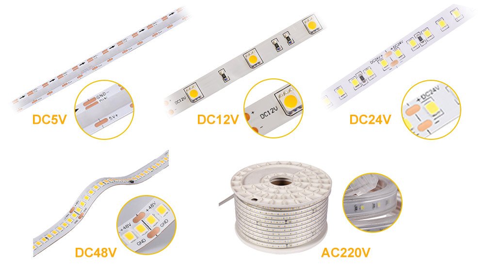
Common LED strip voltages include:
- 5V
- 12V
- 24V
- 36V
- 48V
- Constant-current or specialized high-voltage systems
Voltage should be selected from the required circuit length, current, cut interval, driver availability and safety architecture—not from habit.
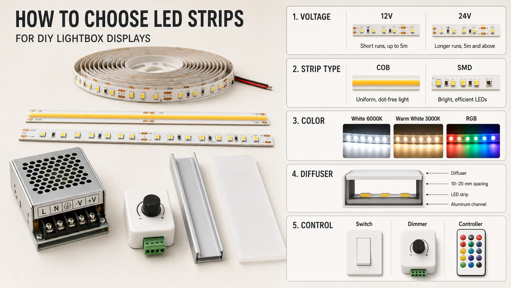
12V LED Strip
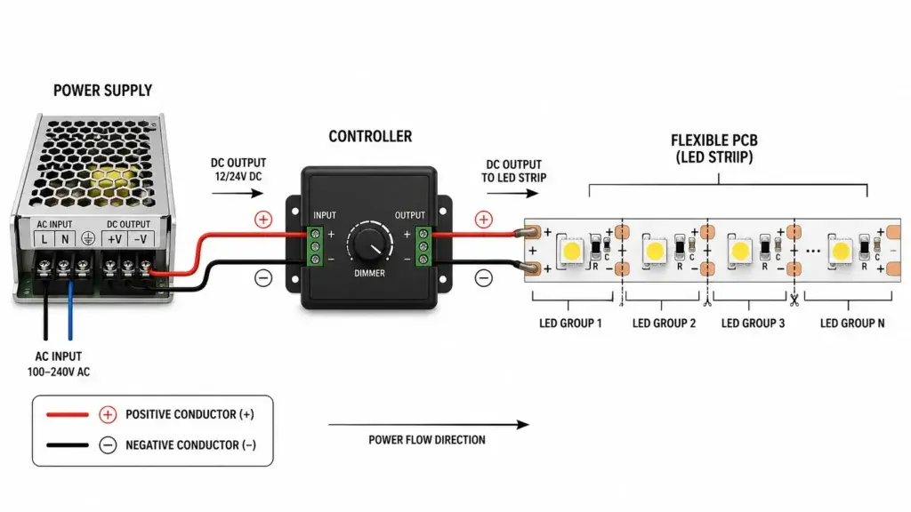
Often suitable when:
- Short cut intervals are important
- Individual sections are relatively short
- Automotive or battery systems are involved
- Compatible 12V components already exist
Trade-offs may include higher current and greater voltage drop for the same power.
24V LED Strip
Often a practical balance between:
- Cut length
- Driver availability
- Circuit current
- Product variety
- Run length
However, 24V does not guarantee that a long strip can be powered from one end.
48V LED Strip
Can reduce current for a given power and may support longer circuit architectures.
Potential trade-offs include:
- Longer cut units
- Fewer compatible drivers or controllers
- Different safety or control constraints
- Greater voltage across each segment
- More complex field replacement requirements
The cheapest strip price per meter may not produce the lowest installed cost. A higher-voltage system can reduce feed cables, driver locations and installation labor—but only when the project layout supports it.
Step 10: Calculate Power and Current
For each branch:
Branch power = strip wattage per meter × branch length
For a constant-voltage load:
Branch current = branch power ÷ operating voltage
For the complete project:
Total connected load = sum of all branch loads
Example:
- Strip load: 9.6 W/m
- Branch length: 4 m
- Voltage: 24V
Branch power:
9.6 W/m × 4 m = 38.4 W
Nominal branch current:
38.4 W ÷ 24V = 1.6 A
Repeat the calculation for every branch rather than using only the total project length.
Rated Power Versus Measured Power
A strip may draw less than its nominal wattage after installation because of:
- Voltage drop
- Driver output tolerance
- Component tolerance
- Thermal behavior
- Controller losses
- Product-level power-limiting design
- Measurement position and method
The specification should state whether wattage is:
- Nominal
- Maximum
- Typical
- Measured at the driver
- Measured at the strip input
- Measured per reel
- Measured after thermal stabilization
Step 11: Size the Driver as Part of the System
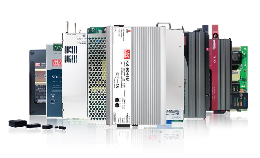
Do not treat “add 20%” as a universal engineering rule.
A preliminary estimate is often calculated as:
Preliminary driver capacity = connected load ÷ selected loading ratio
For example, using an 80% design loading ratio:
100 W ÷ 0.80 = 125 W
But final driver selection should also verify:
- Manufacturer loading requirements
- Ambient-temperature derating
- Enclosure conditions
- Minimum load
- Dimming compatibility
- Inrush current
- Channel capacity
- Output-voltage tolerance
- Cable losses
- Applicable electrical classification
- Surge and protection requirements
- Future expansion, if genuinely required
An oversized driver does not force excessive power into a properly designed constant-voltage strip. However, extreme oversizing may create problems with minimum load, dimming behavior, efficiency, physical size, protection coordination and cost.
Use the LED strip power supply calculator for preliminary sizing, then validate the selected driver against its manufacturer’s data.
Step 12: Check Voltage Drop and Feed Method
Voltage drop can cause:
- Reduced brightness
- Uneven output
- Color shift
- Different RGB mixing along the run
- Lower measured power
- Unstable operation near the end of a circuit
For a two-conductor DC cable, a simplified cable-voltage-drop calculation is:
Voltage drop = 2 × one-way cable length × current × conductor resistance per unit length
The strip itself is more complex because current decreases along the PCB as each LED section consumes power.
Therefore, a professional design should evaluate:
- Driver-to-strip cable loss
- Voltage loss along the PCB
- Connector and joint resistance
- Feed location
- Branch current
- Supply-voltage tolerance
- End-of-run voltage
- Allowed brightness or color variation
Possible solutions include:
- Shorter electrical branches
- Power injection
- Center feeding
- Feeding from both ends
- Higher operating voltage
- Wider PCB
- Heavier copper construction
- Larger cable conductors
- Lower wattage per meter
- More local drivers
Double-ended feeding does not automatically double the valid run length. The result depends on strip construction, current distribution, cable losses and the acceptable end-to-end variation.
Use the LED strip voltage-drop and power-injection calculator to create a preliminary feed plan.
Step 13: Engineer the Thermal Path
LED density, wattage and waterproof construction can all influence temperature, but none of them predicts temperature alone.
The builder should record:
- Maximum ambient temperature
- Installation orientation
- Profile type
- Mounting-surface material
- Enclosure condition
- Airflow
- Waterproof encapsulation
- Maximum permitted PCB or Tc temperature
- Measurement point
- Stabilization time before measurement
An aluminum profile can improve heat spreading, protect the strip and improve optical appearance. It does not guarantee safe temperature if:
- The profile is too small
- The strip wattage is excessive
- Contact between strip and profile is poor
- The profile is enclosed
- Ambient temperature is high
- Waterproof materials retain heat
- The profile itself cannot release heat to the environment
Select the LED aluminum profile together with the strip rather than after the strip has already been approved.
Step 14: Define Flicker and Dimming Performance at System Level
Flicker is not solely a strip characteristic.
Temporal light modulation can be affected by:
- Driver topology
- PWM frequency
- PWM depth
- Dimming method
- Dimmer compatibility
- Load level
- Minimum dimming level
- Controller behavior
- Camera shutter settings
- Mains quality
A “flicker-free strip” claim is therefore incomplete unless the driver and controller are included.
The specification should state:
- Required dimming range
- Minimum stable dimming level
- Control protocol
- Approved driver and controller
- Test load
- Test dimming points
- Camera requirements
- Applicable flicker metrics or regulatory criteria
The U.S. Department of Energy’s flicker research shows why the complete source-driver-control system and operating condition must be considered.
The Specification Conflict Engine
A professional builder should not simply accept incompatible requests. It should identify conflicts and request a decision.
Common Conflict 1: Long One-End Run + 12V + High Wattage
Likely consequences:
- High current
- Greater voltage drop
- Visible brightness loss
- Larger feed cables
Possible responses:
- Divide the run
- Add power injection
- Use center feeding
- Move to 24V or 48V
- Reduce wattage
- Validate a heavier PCB construction
Common Conflict 2: Narrow PCB + High Power + No Profile
Likely consequences:
- Concentrated heat
- Greater voltage drop
- Reduced reliability
- Adhesive failure
Possible responses:
- Reduce wattage
- Use a wider PCB
- Increase copper construction
- Add a suitable profile
- Shorten branches
Common Conflict 3: Direct View + Shallow Profile + Low-Density SMD
Likely consequence:
- Visible LED dots
Possible responses:
- Use a deeper profile
- Increase diffusion
- Reduce LED pitch
- Use COB or CSP
- Increase viewing distance
- Request an optical mock-up
Common Conflict 4: IP68 + Field Cutting
Cutting can invalidate the tested encapsulation and expose conductors.
Possible responses:
- Factory-finished lengths
- Factory-molded cable entries
- Qualified sealing procedure
- Replaceable dry connection zone
- Project-specific immersion testing
Common Conflict 5: Waterproof Strip + High Wattage + Sealed Profile
Likely consequence:
- Heat trapped by both encapsulation and enclosure
Possible responses:
- Lower power
- Larger thermal profile
- External mounting
- Thermal testing at worst-case ambient
- Different waterproof construction
Common Conflict 6: Highest CRI + Highest Efficacy + Lowest Cost
These objectives may conflict because spectrum design, phosphor selection, LED binning and operating current affect output, efficacy and cost.
The builder should ask which requirement has priority.
Common Conflict 7: 48V + Very Short Cut Length
Higher-voltage strips may require more LEDs per electrical section, producing a longer cut interval.
Possible responses:
- Accept longer cut units
- Redesign segment dimensions
- Use 24V
- Use a specialized constant-current architecture
- Develop a custom circuit if quantity justifies it
Common Conflict 8: DALI Tunable White + “Any Tunable White Strip”
The selected driver or controller must support the intended channel and color-control architecture.
Possible responses:
- Use a DALI DT8 Tc device
- Use two coordinated DT6 channels where the system permits
- Confirm channel current and common-anode/common-cathode architecture
- Validate controller-to-strip wiring
Common Conflict 9: Class 2 Requirement + One Large High-Power Circuit
A high total project wattage may need to be divided into multiple compliant branches.
The applicable standard, output classification, driver construction and destination-market requirements should be reviewed before final circuit design.
Common Conflict 10: 50,000-Hour Claim Based Only on LED Data
LED package lumen-maintenance data does not prove the lifetime of the complete strip system.
The strip can fail first because of:
- Resistors or current-control components
- Solder joints
- PCB fatigue
- Connectors
- Cable entries
- Adhesive
- Encapsulation
- Corrosion
- Driver failure
- Thermal stress
IES LM-80 and TM-21 apply to solid-state light-source lumen maintenance and projection. They should not automatically be presented as complete strip, luminaire or system lifetime. The IES position on LED product lifetime explains this distinction.
Stage 3: Define How the Specification Will Be Verified
A specification is incomplete if it gives a value without defining the evidence required to prove it.
Step 15: Classify Every Requirement
Use four priority levels.
Hard Constraint
A requirement that cannot change.
Examples:
- Maximum PCB width: 8 mm
- Maximum profile depth: 10 mm
- Operating voltage: 24V
- Destination market: United States
- Fixed millwork cut-out
- Required control system
Performance Requirement
A measurable result the system must achieve.
Examples:
- Minimum installed output
- Maximum voltage variation
- Minimum dimming level
- Maximum stabilized temperature
- Required CCT tolerance
- Required ingress protection
Preference
A desirable feature that can be traded against cost, lead time or another requirement.
Examples:
- Preferred reel length
- Preferred connector style
- Preferred LED package
- Preferred PCB color
Open Item
A decision or value that has not yet been confirmed.
Examples:
- Final profile selection
- Driver location
- Maximum ambient temperature
- Chemical exposure
- Certification scope
- Final cable length
This prevents an unconfirmed assumption from being treated as an approved specification.
Step 16: Assign a Status to Every Technical Value
Each field should be labeled as one of the following:
- User supplied
- Calculated
- Supplier to propose
- Supplier to validate
- Project team to confirm
For example:
| Field | Value | Status |
| Total illuminated length | 18 m | User supplied |
| Number of branches | 3 | Calculated |
| Operating voltage | 24V | Supplier to validate |
| Maximum run per feed | 6 m | Supplier to validate |
| Driver capacity | 240 W total | Preliminary calculation |
| Profile model | Open | Project team to confirm |
This makes the generated specification auditable and reduces silent assumptions.
Step 17: Request the Right Evidence
Depending on project risk, request:
- Product datasheet
- IES or LDT photometric file
- Integrating-sphere report
- Spectrum report
- TM-30 report
- CCT and SDCM data
- Electrical test report
- Thermal test report
- IP test report
- UV or chemical compatibility data
- Material declaration
- Safety certificate
- CB report or certificate
- RoHS documentation
- Driver compatibility statement
- Dimming test results
- Production inspection report
- Golden sample
- Change-control declaration
Certification must apply to the exact product model and configuration offered. A supplier’s general certificate does not automatically cover every voltage, PCB, waterproof construction, cable and custom version.
For North American projects, requirements may involve standards such as UL 2108 or UL 8750 depending on the product and system architecture. Use the UL lighting safety guidance to identify the relevant certification path rather than adding a generic “UL required” line.
Step 18: Define Sample Acceptance Before Mass Production
A free sample has little value if there is no acceptance procedure.
Record:
- Sample model and revision
- Measured input voltage
- Measured power per meter
- Stabilization time
- Ambient temperature
- CCT and color-quality results
- Brightness and uniformity
- Dimming behavior
- End-of-run performance
- Connector temperature
- Adhesive and mechanical fit
- Profile and diffuser appearance
- Waterproof joint construction
- Cable exit and polarity
- Packaging and label review
For custom products, approve a signed or digitally recorded golden sample.
The golden sample should reference:
- Product code
- BOM or revision
- Approval date
- Approved dimensions
- Electrical values
- Color bin
- Cable configuration
- Waterproof construction
- Packaging
- Approved exceptions
A visual sample alone is not enough if electrical, thermal or compliance characteristics are important.
What the Builder Should Generate
A completed LED Strip Specification Builder should create four connected outputs.
Output 1: Project Design Brief
Include:
- Project name
- Application
- Lighting intent
- Visual conditions
- Installation geometry
- Environmental exposure
- Hard constraints
- Performance priorities
- Unresolved decisions
- Project revision and date
Output 2: LED Strip Product Specification
Include:
| Category | Required field |
| Light source | SMD, COB, CSP or supplier proposal |
| Color mode | Fixed white, tunable white, RGB, RGBW, RGBCCT or addressable |
| Nominal CCT | Required value or range |
| Color tolerance | SDCM, coordinates or approved bin |
| Color quality | CRI, R9, TM-30 or spectrum criteria |
| Output | Minimum lumens per meter and test conditions |
| Power | Nominal or maximum W/m |
| Voltage | 12V, 24V, 48V or other |
| Maximum run | Per feed and under defined conditions |
| PCB | Width, color, copper requirement where necessary |
| Cut length | Maximum permitted cut unit |
| Dimensions | Width, height and tolerance |
| IP construction | Required construction and exposure |
| Temperature | Ambient and maximum measured point |
| Cable | Length, gauge, polarity and exit |
| Connector | Type and rated current |
| Reel | Maximum reel length and electrical-use restrictions |
| Lifetime | Claim basis and test evidence |
| Warranty | Conditions and exclusions |
Output 3: System Integration Schedule
Include:
- Driver model or required characteristics
- Driver quantity
- Loading per driver
- Branch arrangement
- Feed locations
- Cable conductor size
- Maximum cable distance
- Controller model
- Control protocol
- Channel allocation
- Profile and diffuser
- Dimming range
- Circuit protection
- Installation notes
- Service-access requirements
The reel length and electrical run length must be shown separately. A 20-meter reel does not mean the full 20 meters can be powered from one end.
Output 4: Validation and Submittal Schedule
Include:
| Requirement | Acceptance criterion | Evidence | Responsibility |
| Installed output | Minimum specified value | Photometric test or mock-up | Supplier/project team |
| CCT | Within approved tolerance | Spectrum report | Supplier |
| Power | Within declared range | Electrical measurement | Supplier |
| Voltage drop | Within project limit | Calculation and site test | System designer |
| Temperature | Below approved maximum | Stabilized thermal test | Supplier/project team |
| Dimming | Stable across required range | Compatibility test | Controls integrator |
| IP construction | Meets specified test scope | Model-specific report | Supplier |
| Certification | Exact offered model covered | Certificate and scope | Supplier |
| Production consistency | Matches golden sample | Pre-shipment inspection | Supplier/buyer |
Example: Generated LED Strip Project Specification
The following is an example only. Its values should not be treated as universal recommendations.
Project Design Brief
Project: Hotel cove lighting
Visual length: 18 m continuous line
Electrical layout: Three 6 m branches
Lighting role: Indirect ambient lighting
CCT: 3000K
Control: DALI dimming
Environment: Dry indoor
Driver location: Accessible ceiling service zone
Priority: Smooth, consistent light with stable low-level dimming
Hard Constraints
- 24V constant-voltage system
- Maximum PCB width: 10 mm
- DALI building-control integration
- Maximum individual electrical branch: 6 m
- Driver must remain accessible for maintenance
Performance Requirements
- Minimum installed output to be confirmed by cove mock-up
- Initial color consistency: project-approved tolerance
- Stable dimming from 100% to the project-defined minimum level
- No objectionable end-to-end brightness difference
- Stabilized strip temperature below the approved project limit
- Repeat production to match the approved golden sample
Preliminary Electrical Calculation
Assumed strip load:
9.6 W/m
Power per 6 m branch:
9.6 W/m × 6 m = 57.6 W
Current per branch at 24V:
57.6 W ÷ 24V = 2.4 A
Total connected load:
57.6 W × 3 = 172.8 W
The driver arrangement should then be selected after checking:
- Required loading ratio
- DALI interface
- Channel configuration
- Ambient derating
- Cable losses
- Dimming behavior
- Inrush current
- Service strategy
The project should not select a driver solely by rounding 172.8 W to the next available wattage.
Supplier Validation Required
- Actual maximum strip power
- Six-meter end-of-run voltage
- End-to-end output variation
- Required feed arrangement
- Profile thermal compatibility
- Stabilized operating temperature
- Driver and controller compatibility
- Minimum stable dimming level
- CCT and color-consistency data
- Production and repeat-order binning plan
Required Submittals
- LED strip datasheet
- Electrical test report
- Spectrum or color report
- Profile drawing
- Driver datasheet
- DALI compatibility information
- Voltage-drop calculation
- Thermal test result
- Physical sample
- Final golden-sample record
Supplier Response Format
Every supplier should respond to each specification line using one of four statuses:
- Comply
- Comply with exception
- Alternative proposed
- Not available
The response should also include:
- Offered value
- Test condition
- Evidence reference
- Exception explanation
- Effect on price
- Effect on lead time
- Effect on certification
- Effect on performance
This is far more useful than receiving a datasheet with highlighted marketing claims.
Questions to Ask Before Releasing the RFQ
Before sending the specification to suppliers, confirm:
- Are visual length and electrical run length separated?
- Is the required output measured before or after the diffuser?
- Are color requirements more specific than “warm white”?
- Has the actual environmental exposure been defined?
- Are the strip, driver, controller and profile treated as one system?
- Is the voltage-drop limit stated?
- Are driver loading and derating conditions defined?
- Is dimming performance tested at the required load and dimming levels?
- Does certification cover the exact offered configuration?
- Has sample acceptance been defined?
- Are open items clearly marked?
- Is there a revision and change-control process?
If the answer to several of these questions is no, the project is not ready for price comparison.
Frequently Asked Questions
What information is needed to specify an LED strip?
At minimum, provide the application, segment lengths, lighting effect, CCT or color mode, output target, operating environment, available mounting dimensions, control method and destination market. The supplier can then propose technical details such as voltage, PCB construction and feed arrangement.
Should I specify watts per meter or lumens per meter?
Use both when possible.
Watts per meter helps calculate electrical load and heat. Lumens per meter describes light output. For functional lighting, also define the required installed illuminance or delivered output after the profile and diffuser.
Does a higher LED density always mean a better strip?
No. Higher density can reduce visible spacing and improve optical uniformity, but it can also increase cost, circuit complexity and heat concentration. Brightness depends on LED efficacy, drive current, thermal conditions and optical construction—not density alone.
Is COB always better than SMD?
No. COB can provide a more continuous emitting surface and is useful in shallow or visible applications. SMD may offer advantages in efficacy, high output, specialized colors, addressable control, thermal flexibility or serviceability. The correct choice depends on the system.
Is 24V always better than 12V?
No. A 24V strip generally draws less current than a 12V strip of equal wattage, which can reduce voltage drop. However, 12V may offer shorter cut units or better compatibility with certain power systems. Circuit layout should determine the voltage.
How much extra capacity should an LED driver have?
There is no universal percentage suitable for every driver and installation. Calculate the connected load, then check the driver manufacturer’s loading, ambient derating, minimum-load, dimming and inrush requirements. A preliminary 20% allowance may be used for estimation, but it is not a substitute for final validation.
Does IP68 mean an LED strip can be installed in a swimming pool?
Not automatically. IP68 testing does not by itself establish long-term resistance to chlorine, saltwater, UV, field joints or the electrical safety requirements of a pool. The complete system and local regulations must be reviewed.
Can I cut a waterproof strip on site?
Only when the product is designed for field cutting and an approved sealing method is available. Cutting can invalidate the original waterproof construction. Factory-finished lengths are preferable for demanding wet or submerged installations.
Does an aluminum profile prevent overheating?
Not by itself. The profile must have suitable thermal capacity and contact with the strip, and it must be able to release heat into the surrounding environment. Enclosed or insulated profiles can still operate at excessive temperatures.
Can an LED strip itself be DALI or Matter compatible?
Usually the control capability comes from the driver, controller or gateway rather than the passive strip. The complete control chain must be specified and tested.
Does LM-80 prove that an LED strip will last 50,000 hours?
No. LM-80 measures lumen-maintenance behavior of solid-state light sources under defined conditions. It does not directly test the complete LED strip, driver, connectors, adhesive, encapsulation or installation.
From Specification to a Manufacturable Product
A useful specification should reduce uncertainty for both the buyer and the manufacturer.
Xmart Lighting can review project requirements involving:
- 12V, 24V and 48V strip architectures
- SMD and COB constructions
- Custom PCB widths
- Custom wattage and cut lengths
- Fixed white, tunable white and multicolor systems
- Indoor and waterproof constructions
- Cable and connector customization
- LED drivers and controllers
- Aluminum profiles
- Private labeling and packaging
- Sample and production requirements
Custom capability does not mean every requested combination should be manufactured exactly as entered. The first engineering task is to identify conflicts between voltage, run length, cut interval, PCB width, heat, output, environmental protection and certification.
Prepare the specification first, then submit it through the Xmart Lighting quick quote form. Include the segment drawing, driver location, control protocol, environmental exposure and required test evidence whenever possible.