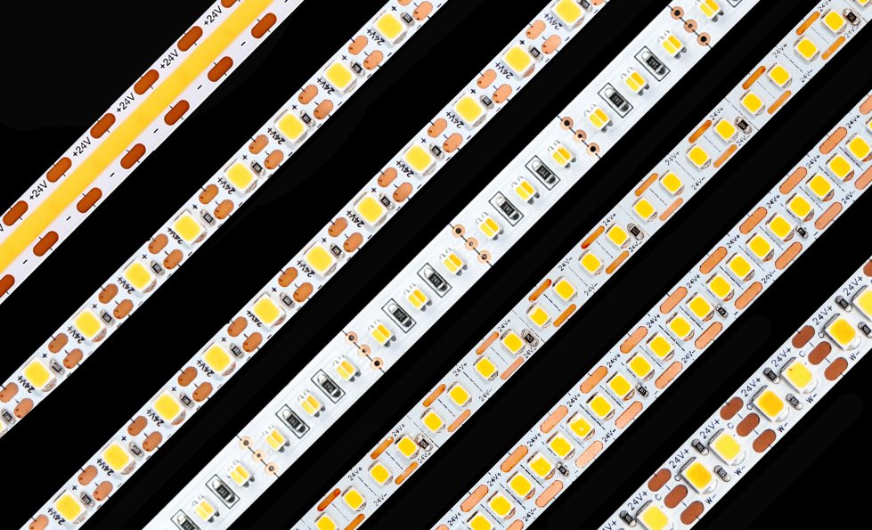
Choosing an LED strip power supply looks simple:
Strip wattage per meter × total length = required watts
That calculation is necessary, but it is not enough.
A reliable driver selection must also account for:
- System voltage
- Maximum credible operating load
- Strip wattage tolerance
- Driver temperature derating
- Dimming and controller limits
- Number of parallel branches
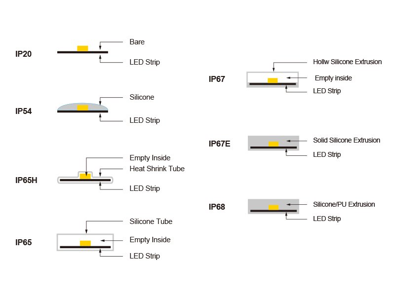
- Dry, damp or wet location
- Voltage drop between the driver and strip
- Required electrical classification
- Inrush current on the AC circuit
Use the calculator below to determine the connected load, output current and preliminary driver size. Then use the engineering guide to decide whether that wattage should be supplied by one driver or divided across several outputs.
This calculator is intended for constant-voltage LED strips. Do not use it to select a constant-current driver unless the LED product manufacturer provides a compatible current and voltage range.
LED Strip Power Supply Calculator
Step 1: Enter the LED Strip Voltage
Select the rated input voltage shown on the LED strip:
- 5V DC
- 12V DC
- 24V DC
- 36V DC
- 48V DC
The driver output voltage must match the strip voltage.
Do not connect:
- A 12V strip to a 24V driver
- A 24V strip to a 48V driver
- A constant-voltage strip to an incompatible constant-current driver
Step 2: Enter the Strip Power
Enter the rated maximum power:
- Watts per meter, or
- Watts per foot
Use the maximum declared wattage for initial design unless the manufacturer provides a validated lower system value.
Step 3: Enter the Total Length and Quantity
Enter:
- Length of each run
- Number of identical runs
- Total illuminated length
For parallel branches:
Total length = length per branch × number of branches
The calculator should also retain the branch length because total driver power and maximum single-run length are different limitations.
Step 4: Select the Maximum Operating Condition
Choose the load condition that represents the highest permitted output:
- Single-color strip at 100%
- Tunable white at maximum permitted combined output
- RGB at full white
- RGBW at maximum permitted combined output
- RGBCCT at maximum permitted combined output
- Addressable strip at full output
- Addressable strip with a permanent software brightness limit
- Custom load factor
Do not estimate the driver from the scene normally displayed during demonstrations. Use the highest load the final control system can produce.
Step 5: Add Design Headroom
Select a headroom value:
- 0%
- 10%
- 15%
- 20%
- 25%
- Custom
A 15–20% allowance is a common preliminary choice, but it is not a universal requirement. The correct allowance depends on the driver datasheet, ambient temperature, strip tolerance, duty cycle and project requirements.
Step 6: Enter the Driver Derating Factor
If the selected driver delivers less than 100% of its nameplate output at the expected temperature or mounting condition, enter the available-output percentage from its datasheet.
Examples:
- 100% available output: enter 100%
- 90% available output: enter 90%
- 80% available output: enter 80%
Do not invent a derating percentage. Use the curve for the exact driver model, input voltage, mounting orientation and ambient temperature.
Calculator Results
The calculator should display:
- Connected strip wattage
- Maximum strip current
- Wattage including selected headroom
- Required driver nameplate wattage after derating
- Recommended next available driver size
- Estimated driver loading percentage
- Current per branch
- Warning if one branch exceeds the connector or controller limit
- Reminder to check maximum LED strip run length
- Reminder to calculate cable voltage drop
- Recommendation to split the load when appropriate
The Four Calculations
1. Connected LED strip load
Connected load = watts per meter × total length
Example:
- Strip power: 9.6W/m
- Total length: 15m
9.6W/m × 15m = 144W
2. LED strip current
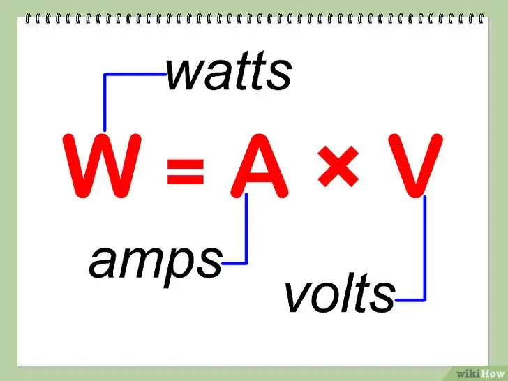
Current = watts ÷ voltage
For a 144W load:
| System voltage | Calculated current |
|---|---|
| 12V | 12A |
| 24V | 6A |
| 48V | 3A |
The power is the same, but the current changes substantially.
This current affects:
- Feed-wire size
- Connector selection
- Controller capacity
- PCB loading
- Power-injection requirements
3. Load including headroom
Design load = connected load × (1 + headroom)
For a 144W strip load with 20% headroom:
144W × 1.20 = 172.8W
The preliminary driver must provide at least 172.8W of usable output under the expected operating conditions.
4. Required driver size after temperature derating
If the driver can provide only 80% of its nameplate output at the project temperature:
Required nameplate wattage = design load ÷ available-output factor
172.8W ÷ 0.80 = 216W
The next suitable standard driver size must be at least 216W. A 240W model might be selected if its voltage, current, environmental rating, dimming method and compliance all match the project.
The Complete Formula
For a constant-voltage LED strip:
Required driver nameplate wattage = W/m × length × quantity × load factor × (1 + headroom) ÷ derating factor
Where:
- W/m = maximum strip power per meter
- Length = length of each strip run
- Quantity = number of identical runs
- Load factor = maximum permitted output condition
- Headroom = design allowance expressed as a decimal
- Derating factor = available driver output expressed as a decimal
Example:
- 12W/m
- 8m per branch
- 2 branches
- 100% maximum load
- 15% headroom
- 90% driver output available at expected ambient
Calculation:
12 × 8 × 2 × 1.00 × 1.15 ÷ 0.90 = 245.3W
The selected driver or combined driver outputs should provide at least 245.3W under those conditions.
That does not automatically mean one 250W driver is the best architecture. Branch protection, controller capacity, run length and serviceability may justify using two smaller drivers.
Why “Add 20%” Is Not a Universal Rule
The familiar rule is:
LED load × 1.2 = power-supply size
It is useful for preliminary planning, but it is not an electrical law.
A 20% allowance may help accommodate:
- Strip wattage tolerance
- Driver operating temperature
- Small design changes
- Long-term component variation
- Avoiding continuous operation at the absolute limit
However, the correct margin may be different when:
- The driver is rated for continuous full output
- The driver has a significant ambient-temperature derating curve
- The strip has a wide power tolerance
- The system has a permanently enforced brightness limit
- The driver must operate inside a hot enclosure
- Redundancy is more important than wattage margin
- The project standard defines a specific loading limit
The driver manufacturer’s data takes priority over a generic 80% loading rule.
MEAN WELL’s LED power-supply guidance recommends considering operating margin and temperature, while its installation instructions require users to follow the exact model’s derating curve when ambient temperature or mounting orientation increases internal temperature. See the MEAN WELL LED power-supply installation manual.
Headroom and Derating Are Not the Same Thing
These two adjustments are frequently confused.
Headroom
Headroom is a design decision.
It creates capacity above the expected connected load.
Derating
Derating is a restriction in the driver datasheet.
It reduces the output that the driver can safely provide under a defined condition.
Assume:
- Driver nameplate: 200W
- Available output at project ambient: 80%
Usable output:
200W × 0.80 = 160W
If the connected strip load is 150W, the driver appears to have 50W of nameplate capacity remaining. In reality, only 10W remains under the derated condition.
Do not calculate 20% headroom and then ignore the driver’s temperature derating.
Conversely, do not apply multiple arbitrary safety factors without understanding them. Excessive oversizing can increase cost and create control or fault-management problems without improving normal operation.
A Larger Driver Does Not Push Too Much Power Into the Strip
A constant-voltage power supply does not normally force its full rated wattage through the LED strip.
A 24V, 240W driver means the unit can provide up to approximately:
240W ÷ 24V = 10A
If a correctly designed 24V strip load requires only 4A, it will normally draw approximately 4A—not 10A.
The power rating is available capacity.
However, a much larger driver can provide more current during a fault. This can make the following more important:
- Output fusing
- Branch protection
- Wire size
- Connector rating
- Short-circuit behavior
- Class 2 or limited-power requirements
A larger driver is not automatically dangerous, but it is not automatically safer either.
Why an Oversized Driver Can Still Be a Poor Choice
Selecting the largest available power supply may cause:
- Higher purchase cost
- Larger enclosure requirements
- More heat inside one location
- Higher available fault current
- Poor low-load efficiency
- Dimming instability on some driver types
- Failure to meet minimum-load requirements
- A larger dark area if the single driver fails
- More difficult Class 2 or branch segmentation
Some phase-cut and legacy dimmable drivers perform poorly below a defined minimum load. A heavily oversized driver may therefore produce worse low-end dimming than a correctly sized model.
Check:
- Minimum load
- Dimming range
- Dimming curve
- Standby power
- Efficiency at partial load
- No-load behavior
Driver Efficiency Should Not Be Added to the Output Wattage
Assume:
- LED strip output load: 144W
- Driver efficiency at that load: 90%
The approximate AC input power is:
144W ÷ 0.90 = 160W
The 16W difference is largely dissipated as heat in the driver.
However, driver efficiency does not mean the LED strip needs a 160W output to receive 144W.
Driver output rating and AC input consumption are different calculations:
- Use DC output capacity to size the strip driver.
- Use efficiency, power factor, input current and inrush current to design the AC supply circuit.
Do not add the driver’s efficiency loss to the LED load twice.
Rated Strip Power vs Measured Power
Suppose a 10m strip is labeled 10W/m.
The rated calculation is:
10W/m × 10m = 100W
During a site test, the installer measures only 72W.
It may be tempting to size the driver from the 72W measurement. That can be a mistake.
The lower result may be caused by:
- Voltage drop
- One-end feeding of an excessive length
- Low driver output voltage
- Controller limitation
- Dimming
- Warm-up behavior
- Product tolerance
- Measurement error
- An inaccurate product specification
If the far end receives insufficient voltage, the strip may draw less power because it produces less light.
Lower measured power is not automatically higher efficiency.
For initial driver selection, use the declared maximum load and tolerance. Use measurements to validate the completed system—not to hide a voltage-drop problem.
Worked Example 1: Single-Color 24V Strip
Project:
- 24V
- 12W/m
- 8m total
- 15% headroom
- Driver available output: 100%
Connected load:
12W/m × 8m = 96W
Current:
96W ÷ 24V = 4A
Design load:
96W × 1.15 = 110.4W
A suitable next driver size may be 120W, provided it can deliver its rated output at the expected ambient temperature.
But the electrical design still needs to confirm whether the specific strip can run 8m from one feed. Power-supply capacity does not prove maximum run length.
Worked Example 2: RGBW Strip
Project:
- 24V RGBW strip
- 19.2W/m maximum declared power
- 10m total
- 20% headroom
Connected load:
19.2W/m × 10m = 192W
Current:
192W ÷ 24V = 8A
Design load:
192W × 1.20 = 230.4W
A 240W driver may appear appropriate.
However, the controller must also support:
- At least 8A combined output
- The maximum current of each channel
- The current through the common conductor
- The permitted load for simultaneous RGBW operation
If the controller is rated 5A per channel but only 6A total, it cannot operate the 8A load even though no individual channel exceeds 5A.
The complete path must be checked:
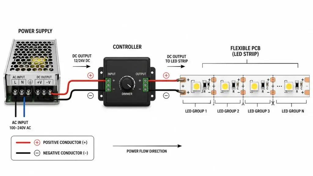
Driver → controller → connector → cable → LED strip
Worked Example 3: High-Ambient Commercial Installation
Project:
- 24V strip
- 9.6W/m
- 20m total across parallel branches
- 15% headroom
- Selected driver provides 80% output at the expected enclosure temperature
Connected load:
9.6W/m × 20m = 192W
Design load:
192W × 1.15 = 220.8W
Required nameplate power after derating:
220.8W ÷ 0.80 = 276W
A driver rated below 276W would not provide the planned output margin at that temperature.
A 320W model may meet the calculation, but three questions remain:
- Should the 20m load be divided across several drivers?
- Can every output branch safely carry its current?
- Would relocating the driver to a cooler, ventilated location remove the severe derating?
Sometimes the best solution is not a larger driver. It is a better driver location.
Worked Example 4: Addressable LED Strip With a Brightness Limit
Project:
- Rated maximum: 18W/m
- Total length: 20m
- Software brightness cap: 40%
The theoretical reduced load is:
18W/m × 20m × 0.40 = 144W
This calculation is acceptable only if the 40% limit is reliably enforced.
Check whether:
- The limit is stored in the controller
- Users can override it
- Firmware updates can remove it
- Boot-up or test modes briefly run at 100%
- Failure modes can activate all channels
- The project specification accepts the limitation
For architectural and public installations, designing for the full credible hardware load is often safer than relying on an app setting.
Tunable-White Loads Need Controller-Specific Calculation
A tunable-white strip has warm-white and cool-white channels.
Some controllers:
- Blend both channels while limiting total output
- Allow both channels to reach 100%
- Maintain constant lumen output
- Maintain constant electrical power
- Apply a custom mixing curve
A strip described as 20W/m may mean:
- 10W/m per channel with 20W/m combined
- 20W/m per channel with 40W/m possible
- 20W/m maximum because the controller limits both channels
Confirm whether the datasheet wattage is:
- Per channel
- Combined rated power
- Maximum allowed simultaneous power
The same issue applies to RGBW and RGBCCT systems.
One Large Driver or Several Smaller Drivers?
Total wattage does not decide the answer by itself.
One large driver can offer:
- Fewer AC connection points
- Centralized maintenance
- Lower equipment count
- Simpler purchasing
But it can also create:
- Long low-voltage cable runs
- More voltage drop
- Higher branch current
- More available fault current
- A larger failure zone
- More difficult load segmentation
Several smaller drivers can offer:
- Shorter DC cable runs
- Easier zoning
- Reduced single-point failure impact
- Better compatibility with power-limited outputs
- Simpler branch current management
But they may require:
- More AC wiring
- More access panels
- More dimming interfaces
- Inrush-current coordination
- Additional commissioning
The lowest-cost driver arrangement is not always the lowest-cost installed system.
When the Load Should Be Split
Consider dividing the load when:
- Strip runs are physically far apart
- Low-voltage cables would be long
- One driver would exceed controller capacity
- Different zones need independent dimming
- Branch protection becomes difficult
- The project requires Class 2 outputs
- Driver access is available near each load
- Redundancy is important
- One failure must not darken the entire installation
For North American projects, “Class 2” must appear as a specific output classification. It should not be inferred merely because the output is 12V, 24V or 48V.
UL explains that LED drivers marked Class 2 meet defined voltage, current, power and isolation criteria under the applicable requirements. See the UL guide information for LED drivers.
One large low-voltage power supply is not automatically equivalent to several Class 2 outputs.
The Driver Must Match the Environment
Check whether the driver is rated for:
- Dry location
- Damp location
- Wet location
- Indoor or outdoor use
- Enclosed installation
- Maximum ambient temperature
- Maximum Tc case temperature
- Required mounting orientation
- Contact with insulation
- Salt or chemical exposure
An IP67 driver can still fail if:
- Its cable connections are not sealed
- It is mounted in standing water
- It exceeds its case temperature
- It is installed against the instructions
- Condensation enters the junction box
- It is exposed to incompatible chemicals
Driver environmental rating and connection-box rating must be evaluated separately.
Do Not Forget Inrush Current
The LED-strip calculator determines DC output capacity. It does not size the upstream AC breaker.
Switch-mode LED drivers can draw a brief inrush current when energized.
A project with many drivers switching on simultaneously can cause:
- Nuisance breaker trips
- Contactor stress
- Relay contact damage
- Unexpected control failures
For large installations, request:
- Maximum input current
- Inrush-current peak
- Inrush duration
- Maximum recommended drivers per breaker
- Circuit-breaker characteristic
- Power factor
- Total harmonic distortion
- Startup sequence
A 1,000W LED installation divided across ten drivers may behave differently at startup from one 1,000W resistive load.
Dimming Compatibility Is Part of Driver Sizing
Confirm the control method:
- PWM
- 0–10V
- DALI
- TRIAC or phase cut
- DMX through a decoder
- RF, Zigbee, Bluetooth or smart controller
The driver may provide:
- Direct dimming
- Constant-voltage output to a downstream PWM controller
- Dimming of its output voltage or current
- A separate control interface
A driver that has sufficient wattage can still be unsuitable because of:
- Incompatible dimming protocol
- Minimum-load behavior
- Insufficient dimming range
- Visible flicker
- PWM interaction
- Controller input-current limits
- Standby behavior
Power capacity is one compatibility requirement—not the entire compatibility test.
Driver Temperature Affects Reliability
A driver is not a lossless box.
Its internal components can include:
- Capacitors
- Transformers
- Inductors
- Rectifiers
- Switching transistors
- Control ICs
- Resistors
The U.S. Department of Energy notes that driver electronics can be an important LED-system reliability concern and that power-supply temperature and component selection affect lifetime. See the DOE LED Luminaire Lifetime Recommendations.
Do not hide the driver:
- Under thermal insulation
- Inside an unventilated ceiling cavity
- Against another heat-producing driver
- Directly above a high-power strip
- In a sealed box without thermal validation
Measure the specified driver Tc point under the final installation condition.
Power-Supply Selection Workflow
Use this order:
1. Confirm strip type
- Constant voltage or constant current
- Rated voltage
- Maximum watts per meter
- Wattage tolerance
2. Calculate maximum connected load
Include every strip and every channel that may operate simultaneously.
3. Calculate output current
Current = watts ÷ voltage
4. Select a justified headroom
Use project requirements and driver data—not habit alone.
5. Apply datasheet derating
Check ambient temperature, input voltage and mounting orientation.
6. Decide the number of drivers
Consider zones, cable length, Class 2 outputs, maintenance and fault impact.
7. Check every downstream component
Verify:
- Controller total current
- Controller current per channel
- Common-terminal current
- Connector rating
- Cable ampacity
- PCB feed limit
- Branch protection
8. Calculate voltage drop
Driver wattage does not correct undersized or excessively long cables.
Use the LED Strip Voltage Drop and Power Injection Calculator for feeder-wire and injection planning.
9. Verify environmental suitability
Confirm dry, damp, wet, temperature and enclosure requirements.
10. Test the complete system
Measure:
- Driver output voltage
- Strip input voltage
- Total current
- Power after warm-up
- Driver case temperature
- Strip temperature
- Dimming performance
- Startup behavior
Information to Send With an LED Driver RFQ
To receive a useful recommendation, provide:
- LED strip model
- Voltage
- Watts per meter
- Total length
- Length of each branch
- Number of zones
- White, tunable white, RGB, RGBW or addressable
- Maximum simultaneous channel operation
- Dimming protocol
- Input voltage and frequency
- Indoor, damp, outdoor or wet location
- Minimum and maximum ambient temperature
- Driver mounting location
- Driver-to-strip cable distance
- Required certification
- Class 2 requirement where applicable
- Redundancy requirement
- Project drawing
Xmart’s LED driver range includes non-dimmable and dimmable options for 12V, 24V and 48V LED strip systems. For commercial projects, Xmart can evaluate the strip, driver, controller, branch loading and wiring architecture as one system rather than quoting the power supply in isolation.

Submit the strip schedule and control requirements through the Xmart project quotation form.
Frequently Asked Questions
What size power supply do I need for LED strips?
Multiply watts per meter by total strip length, include the maximum simultaneous load, add justified headroom and then account for the selected driver’s temperature derating.
How many amps does an LED strip need?
Divide the maximum strip wattage by its rated voltage.
For example:
120W ÷ 24V = 5A
Should I add 20% to LED strip wattage?
A 20% allowance is a useful preliminary rule, but it is not universal. Follow the driver datasheet, temperature derating and project requirements.
Can I use a 100W driver for an 80W LED strip?
Often yes, if the voltage, driver type, operating temperature, environment and dimming method match. This represents 20% nameplate headroom before any required derating.
Can I use a 200W power supply for a 50W strip?
A correctly matched constant-voltage strip will not normally draw the full 200W. However, such oversizing may reduce low-load performance and increase available fault current and cost.
Does a larger power supply make LED strips brighter?
Not when the existing driver already supplies the correct voltage without overload or voltage drop. Brightness is controlled by strip design, voltage at the strip and dimming.
Does a larger power supply solve voltage drop?
No. Voltage drop is addressed through cable size, driver location, higher system voltage, shorter branches or power injection.
Should I size the driver from measured wattage?
Use the declared maximum load and tolerance for initial design. A low measurement may be caused by voltage drop or control limitation.
Is the LED driver wattage its AC power consumption?
No. Driver wattage usually describes available DC output. AC input power is higher because the driver is not 100% efficient.
Can one driver power several LED strips?
Yes, if the strips have the same required voltage and the combined load, current, wiring and control architecture remain within all ratings. Parallel branch wiring is normally preferable to one long daisy chain.
Can I connect two LED drivers in parallel?
Do not directly parallel ordinary driver outputs unless the manufacturer explicitly permits and documents parallel operation. Use separate load sections or drivers designed for current sharing.
Does an RGBW strip need a larger driver than RGB?
It often does because it has an additional white channel, but use the exact maximum combined wattage and controller behavior.
Should I calculate tunable-white wattage per channel?
Confirm whether the datasheet rating is per channel or for the permitted combined output. Different controllers manage the two channels differently.
What happens if the power supply is too small?
It may:
- Enter overload protection
- Cycle on and off
- Flicker
- Reduce output voltage
- Overheat
- Shut down
- Experience shortened lifetime
What happens if the power supply is too large?
Normal operation may remain safe with a properly matched constant-voltage system, but excessive oversizing can increase fault current, cost, size and low-load dimming problems.
Final Answer
The correct LED strip driver is not simply the next power supply above:
W/m × meters
A professional calculation is:
Required driver wattage = connected strip load × maximum operating factor × headroom ÷ available output after derating
Then verify:
- Output voltage
- Output current
- Controller limits
- Branch design
- Cable voltage drop
- Environmental rating
- Dimming compatibility
- Driver temperature
- Electrical classification
- AC inrush current
The best driver is not the largest one that fits the budget. It is the smallest appropriately rated driver—or group of drivers—that can operate the real load, at the real temperature, through the real control and wiring system, with documented capacity remaining.