
PCB Width, Cut Length and Connector Fit for LED Strips
A practical guide for fixture manufacturers, lighting brands and project buyers matching LED strips with profiles, cut dimensions, solder pads, cables and connectors.
Check the Fit RequirementsWhat Must Buyers Check Before Installing an LED Strip?
PCB width alone does not confirm that an LED strip will fit a fixture.
Buyers must check the finished strip width and height, profile clearance, cut-unit length, solder-pad layout, connector dimensions, cable exit and waterproof construction as one complete assembly. Two LED strips can have the same PCB width but use different pad positions, channel counts, thicknesses or connector systems. A connector that matches the nominal width may still be electrically or mechanically incompatible.
The strip may fit the profile while its connector, solder joint or cable exit does not.
The LED Strip Must Fit as a Complete Assembly
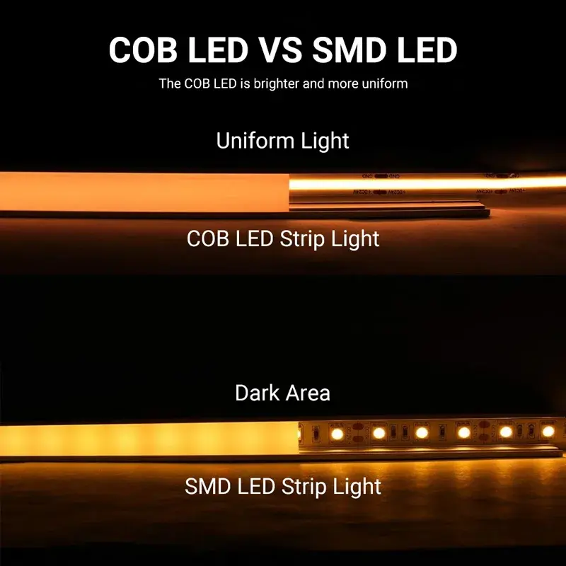
Do not compare the bare PCB width only. The installed assembly may include silicone coating, solder, connector housing, end cap, cable strain relief and manufacturing tolerance.
Critical Cross-Section Dimensions
- Profile external width: Overall footprint of the fixture.
- Profile usable internal width & depth: The actual clear space available.
- Diffuser position & LED distance: Affects light spotting and dotting.
- Bare PCB width vs. Finished strip width/height: Accounts for coatings and components.
- Connector outer width & height: Often the widest point of the assembly.
- Solder-joint height: Must clear the diffuser.
- Cable exit direction & bend allowance: Requires extra routing space.
Which LED Strip Dimensions Should Buyers Confirm?
| Dimension | What It Means | Why It Matters |
|---|---|---|
| Bare PCB Width | The width of the flexible printed circuit board before waterproof coating or external encapsulation. | It affects component space, profile selection and possible connector families, but does not define final installed width. |
| Finished Strip Width and Height | The maximum outer dimensions after coating, tubing, extrusion or other finishing processes. | These dimensions determine whether the finished product—not only the PCB—fits the fixture. |
| Profile Usable Internal Space | The actual clear width and depth available after accounting for diffuser lips, screws, clips and internal features. | The advertised external profile width cannot be used as the strip-fit dimension. |
| Cut-Unit Length | The distance between two permitted cut marks. | It determines which finished illuminated lengths can be produced without redesigning the circuit. |
| Solder-Pad Layout | The number, width, length, pitch and position of the copper pads at the cut point. | The pad layout must align with the connector contacts or the factory soldering process. |
| Termination Envelope | The maximum width, height and length occupied by a connector, solder joint, cable, molded end or strain relief. | The termination may require more space than the LED strip itself. |
Does a Wider LED Strip PCB Perform Better?
Not automatically.
A wider PCB can provide more space for power rails, color channels, components and solder pads. However, electrical performance also depends on copper thickness, effective conductor width, circuit layout, watts per meter and operating temperature.
A narrow strip may be appropriate when installation space is limited, but it can introduce smaller pads, concentrated heat, restricted conductor space and fewer connector options.
| PCB Width | Common Design Reason | Buyer Must Still Verify |
|---|---|---|
| 2–5 mm | Very narrow furniture, display or product-integration spaces | Power, thermal mounting, solder-pad size and connector availability |
| 8 mm | Compact single-color, COB or selected tunable-white designs | Finished width, cut length and profile clearance |
| 10 mm | Additional circuit, pad or component space | Channel layout, connector type and actual power rails |
| 12 mm and wider | Multichannel, larger components, multi-row or higher-current layouts | Profile size, connector dimensions and thermal design |
These are common design uses, not fixed product rules. The correct PCB width is the narrowest practical construction that still satisfies the electrical, thermal, mechanical and production requirements.
Why Does Cut Length Matter in OEM Fixture Design?
An LED strip cannot normally be cut at any arbitrary position. It can be cut only at the designated cut marks that separate valid electrical sections.
Available strip length = whole-number multiple of the model’s cut unit
A supplier should not promise an exact finished length unless that length matches the cut unit or the product has been specifically redesigned.
Note: "Custom cut length" is rarely just a packaging service. Changing the cut unit usually involves modifying the circuit, component layout, power ratings, testing, MOQ, and certification coverage.
Cut-Length Example
Project Requirements:
- Required illuminated length: 1,180 mm
- Proposed strip cut unit: 50 mm
Calculation Result:
- 23 cut units = 1,150 mm
- 24 cut units = 1,200 mm
Conclusion: The proposed strip cannot produce an exact 1,180 mm electrical section.
Possible Decisions:
- Use 1,150 mm and accept a 30 mm unlit area
- Modify the fixture to accept 1,200 mm
- Select another model with a shorter cut unit
- Evaluate a custom circuit if order volume and validation requirements justify it
How Do Buyers Select a Compatible LED Strip Connector?
Matching the connector width is only the first step. A compatible connector must match the complete mechanical and electrical interface.
A 10 mm single-color connector cannot be assumed to fit a 10 mm RGB, tunable-white or COB strip. Equal width does not mean equal pin count, pad geometry or current rating.
Compatibility Checklist
- 1. Strip construction (SMD, COB, etc.)
- 2. Bare PCB width
- 3. Finished strip thickness
- 4. Number of electrical conductors
- 5. Pad count
- 6. Pad pitch and position
- 7. Available copper-pad length
- 8. Maximum operating current
- 9. IP construction and installation environment
Soldered Lead or Solderless Connector?
| Termination Method | Useful When | Buyer Must Check |
|---|---|---|
| Factory-Soldered Lead | Useful when compact dimensions, controlled assembly or higher current requires a direct cable connection. | Check solder quality, insulation, strain relief, cable gauge, cable exit and finished joint height. |
| Solderless Connector | Useful when field installation, replacement or rapid assembly is important. | Check PCB width, pad alignment, current rating, housing dimensions, profile clearance and contact stability. |
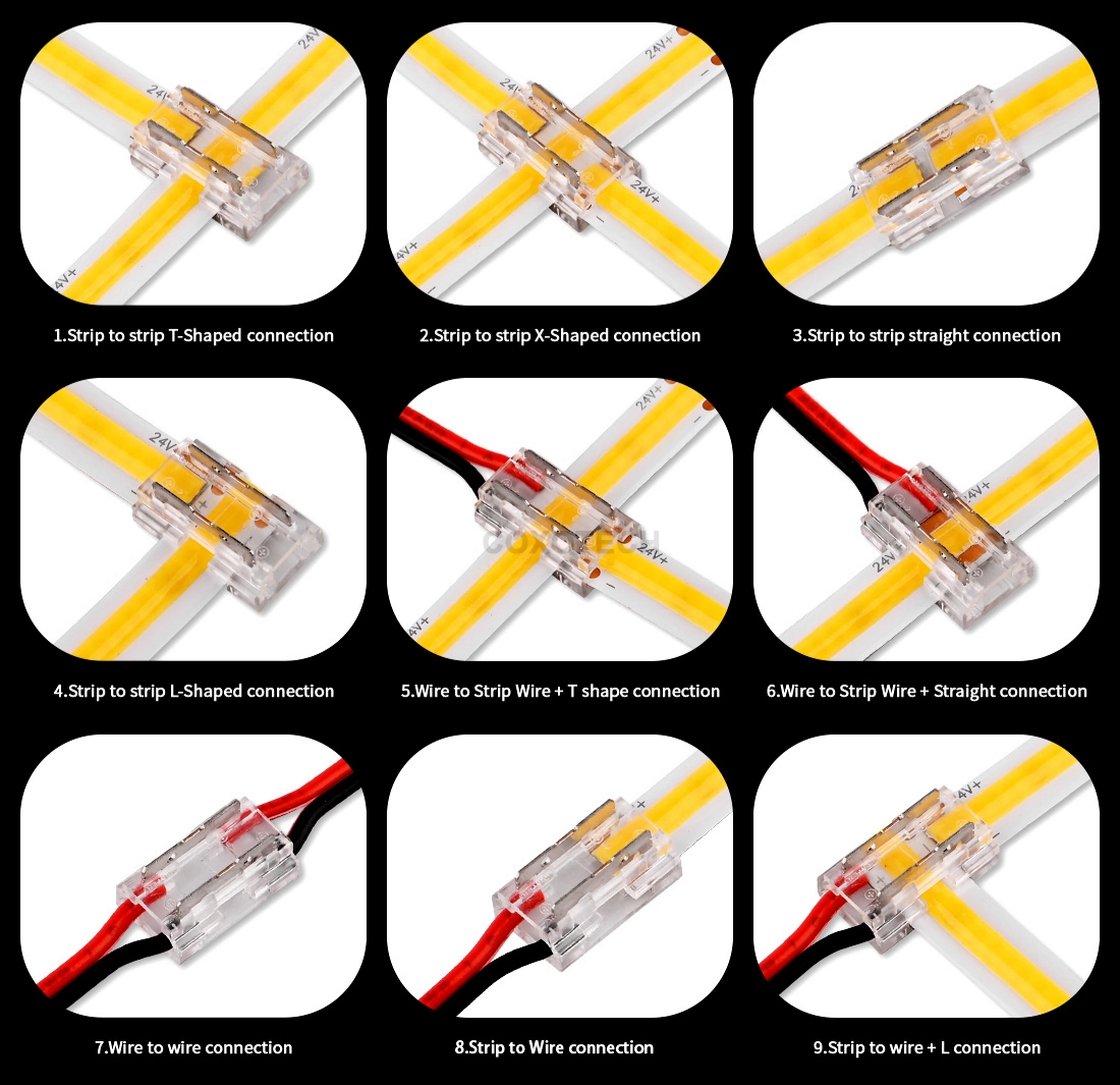
| Strip-to-Strip Connector | Useful when two sections must be joined directly or across a short gap. | Check polarity, channel order, mechanical support and the dark or non-emitting area at the joint. |
| L-Shape or Corner Connector | Useful when a rigid 90-degree layout is required. | Check whether the connector fits inside the profile and whether it creates an acceptable unlit corner. |
| Factory-Molded Waterproof Lead | Useful when the connection must be sealed as part of the finished product. | Check finished dimensions, IP validation, cable direction and whether field cutting is permitted. |
No connection method is universally best. Select the termination according to current, available space, installation environment, service method and production process.
Mechanical Fit Example:
The Strip Fits, but the Connector Does Not
Example Parameters
- Profile usable internal width
- 9.0 mm
- Bare PCB width
- 8.0 mm
- Finished strip width
- 8.4 ±0.2 mm
- Connector outer width
- 12.0 mm
- Cable exit
- Side exit
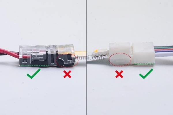
Judgment: The finished strip fits inside the profile, but the 12 mm connector housing does not.
Possible Solutions
-
Use a factory-soldered lead that stays within the profile envelope
-
Create a wider termination pocket outside the profile
-
Select a compatible lower-profile connector
-
Change the profile design
-
Route the connection outside the visible linear section
Illustrative dimensions only. Final decisions must use the proposed strip, connector and profile drawings.
Why Waterproof LED Strips Need Separate Dimension Checks
A waterproof construction can change the strip’s width, height, flexibility, thermal contact and termination method.
Buyers must verify:
Do not order a waterproof “10 mm LED strip” based only on its PCB width.
Request the finished cross-section and termination drawing. Note: Do not assume standard connectors maintain IP ratings after piercing a waterproof layer unless the specific combination has passed validated finished-product testing.
How Should OEM Buyers Approve Mechanical Fit?
Share the Fixture Drawing
Provide the internal width, depth, diffuser, cable path and termination space.
Define the Finished Light Length
Separate the illuminated length from the total fixture or assembly length.
Match the Cut Unit
Confirm that the required length is a valid multiple of the proposed model’s cut unit.
Select the Termination
Choose soldered lead, connector, jumper or molded waterproof end according to the installation.
Review the Dimensioned Drawing
Confirm the strip, pad, connector, wire exit and finished assembly tolerances.
Approve a Physical Sample
Install the actual sample in the intended profile before approving mass production.
What Should Xmart Provide for Fit Verification?
- Exact product model
- Bare PCB width
- Finished strip width and height
- Dimensional tolerance
- Cut-unit length
- Solder-pad drawing
- Channel and polarity diagram
- Compatible connector part number
- Connector outer dimensions
- Connector current rating
- Cable gauge and cable-exit direction
- Waterproof termination details
- Recommended profile clearance
- Approved physical sample reference
* Note: We provide exact connector dimensions and part numbers for validation, rather than generic claims of "compatible connectors available."
LED Strip Fit and Connector Questions
Will any 10 mm connector fit a 10 mm LED strip?
Can LED strip be cut at any length?
Is PCB width the same as finished waterproof width?
Is a wider PCB always better?
Is soldering better than a solderless connector?
Can Xmart customize the cut length?
Why does the LED strip fit the profile but the connector does not?
Check Your LED Strip and Profile Fit Before Sampling
Send Xmart your fixture drawing, required illuminated length, profile dimensions, PCB-width limit, cut-length requirement and preferred termination method. The team can review the mechanical fit before preparing a sample.
Email Us
info@xmartlighting.comCall Us
+86 15874715712Factory Location
Pho Yen City, Thai Nguyen Province, Vietnam