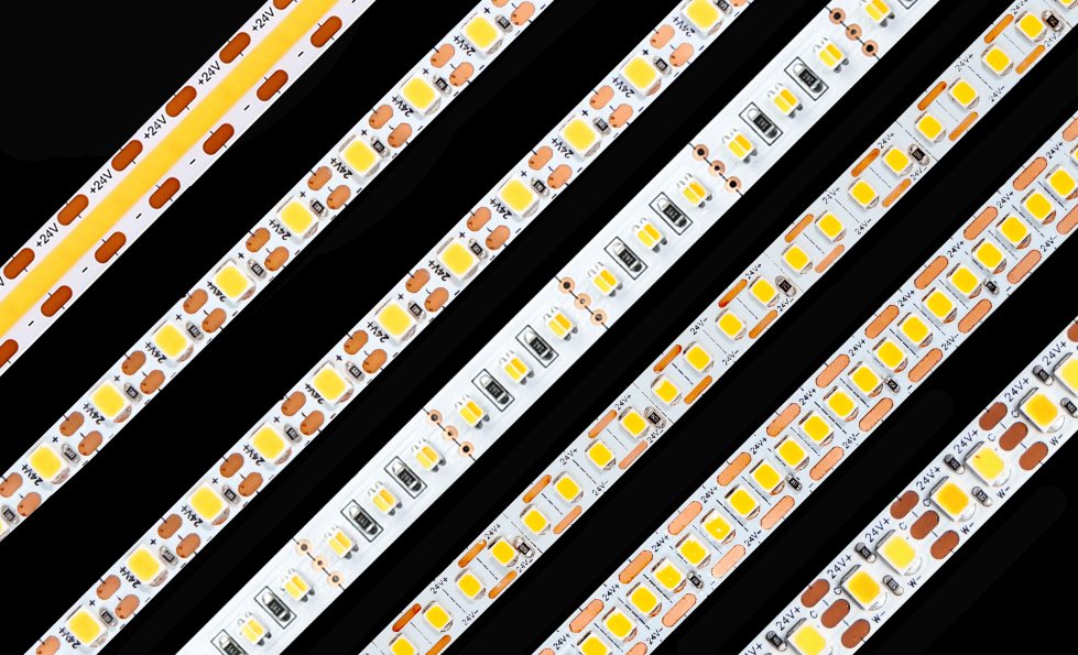
An LED strip usually does not fall because its adhesive is simply “not sticky enough.”
In many failed installations, the real cause is one or more of the following:
- The mounting surface was contaminated
- The adhesive could not wet the substrate
- The substrate had low surface energy
- The tape was applied without sufficient pressure
- The strip was energized before the bond developed
- Heat softened the adhesive and caused creep
- Moisture entered along the tape edge
- The mounting surface itself failed
- Cable tension or corners placed the tape under peel stress
- The adhesive chemistry was incompatible with silicone, plasticizers or surface coatings
Replacing the original tape with a thicker or more aggressive tape may temporarily hide the problem. It does not necessarily correct the underlying failure mode.
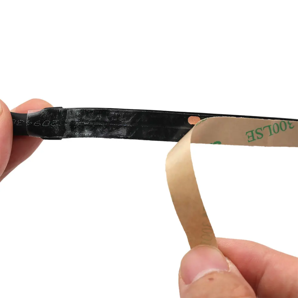
The more useful question is:
Which interface failed, under what stress, and why?
Quick Answer: Why Does LED Strip Tape Peel Off?
LED strip adhesive commonly fails when the tape cannot make sufficient molecular contact with the mounting surface or cannot maintain that contact under heat, moisture and mechanical load.
The four main causes are:
- Poor surface preparation: Dust, oil, oxidation, moisture or cleaning residue prevents proper bonding.
- Wrong tape-to-surface combination: A tape suitable for aluminum may perform poorly on silicone, polypropylene, powder coating or unfinished wood.
- Excessive temperature: Heat reduces adhesive shear strength and accelerates creep, especially on ceilings and vertical surfaces.
- Installation stress: Corners, cables, connectors, uneven surfaces and immediate loading can pull the strip away before the bond develops.
For long-term installations, treat the adhesive as one component of the mounting system—not as a universal replacement for an aluminum profile, clip or mechanical fastener.
First Diagnose Where the Bond Failed
Before cleaning the surface or changing the tape, inspect the failed strip.
The location of the remaining adhesive usually reveals more than the brand name printed on the release liner.
| What you see after failure | Likely failure mode | What it suggests |
|---|---|---|
| Tape remains on the LED strip; mounting surface is clean | Adhesive failure at substrate | Contamination, low surface energy, moisture or incompatible surface |
| Tape remains on the mounting surface; PCB is clean | Adhesive failure at strip side | Poor tape lamination, PCB contamination or unsuitable adhesive |
| Adhesive is divided between both surfaces | Cohesive failure | Adhesive softened, aged or was overloaded |
| Paint, plaster, dust or wood fibers remain on the tape | Substrate failure | The tape was stronger than the surface layer |
| Strip detaches mainly near cables or connectors | Peel or cable stress | Poor strain relief or insufficient support |
| Strip detaches at corners | Bending recovery or peel stress | Bend radius too small or strip forced around a corner |
| Adhesive looks soft, displaced or gummy | Heat or chemical attack | Excessive temperature, plasticizer migration or incompatible cleaner |
| Adhesive looks hard, brittle or discolored | Aging or environmental exposure | Heat, UV, oxidation or incompatible materials |
| Failure starts at the edges | Moisture or contamination ingress | Condensation, cleaning water or poor edge protection |
| Only the hottest sections detach | Thermal creep | Inadequate thermal path or tape with insufficient shear resistance |
This diagnosis separates four different failure categories.
Adhesive Failure
The adhesive separates cleanly from one of the surfaces.
Cohesive Failure
The adhesive layer itself splits internally.
Substrate Failure
Paint, plaster, oxidation, veneer or another weak surface layer separates from the base material.
Mechanical Failure
The tape may be functioning normally, but the installation applies more peel, shear or bending force than the bond can resist.
A “stronger tape” will not repair weak paint, unstable plaster or a badly designed cable exit.
How Pressure-Sensitive Adhesive Actually Works
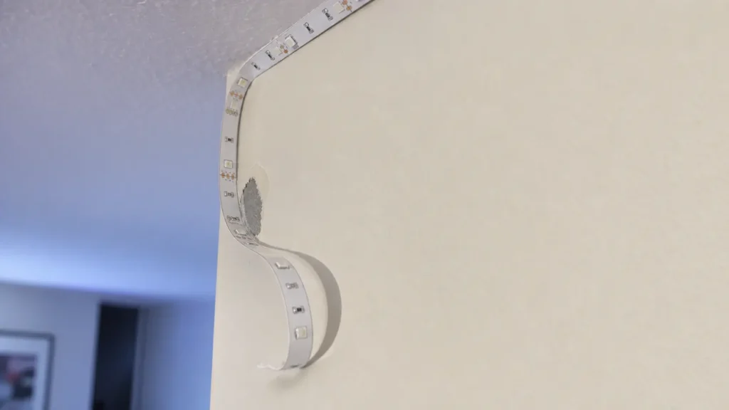
Most LED strip backing tapes use a pressure-sensitive adhesive, or PSA.
A PSA does not normally cure like an epoxy. It bonds when the adhesive flows sufficiently into the microscopic irregularities of the surface. This process is called wet-out.
Effective wet-out depends on:
- Adhesive chemistry
- Surface energy
- Surface cleanliness
- Surface roughness
- Application temperature
- Application pressure
- Contact time
- Tape thickness and conformability
A tape can feel extremely sticky to a finger and still perform poorly on the project substrate. Finger tack is not a reliable measure of long-term peel resistance, shear resistance or environmental durability.
According to 3M’s surface-preparation guidance, firm pressure improves adhesive-to-surface contact, and bond strength can continue increasing after application as the adhesive flows over the surface.
That means an LED strip that feels secure immediately after installation may not yet have developed its final bond strength.
Initial Tack Is Not Long-Term Holding Strength
Four properties are commonly confused.
Tack
How quickly the tape grabs the surface with light contact.
High tack is useful during installation, but it does not prove long-term durability.
Peel Adhesion
Resistance to a force that lifts the tape away from an edge.
Peel stress is particularly important at corners, strip ends, connectors and cable exits.
Shear Strength
Resistance to forces acting parallel to the bonding surface.
A strip mounted vertically or upside down may gradually slide or detach if the adhesive softens under heat.
Cohesive Strength
The ability of the adhesive layer to resist splitting or flowing internally.
An adhesive can have high initial tack but inadequate cohesive strength at the project’s operating temperature.
This explains why some strips attach easily during installation and fall several weeks later.
Cause 1: The Surface Was Not Actually Clean
A surface may look clean while still containing:
- Machining oil
- Fingerprints
- Silicone residue
- Dust
- Detergent film
- Wax
- Mold-release agents
- Oxidation
- Plasticizer
- Moisture
- Residue from a previous adhesive
- Powder from plaster or unfinished wood
The tape bonds to the contamination layer instead of the intended substrate.
Why a Quick Alcohol Wipe May Not Be Enough
Isopropyl alcohol is commonly used for surface preparation, but it is not a universal solution.
Potential problems include:
- A dirty cloth redistributes oil instead of removing it
- Low-purity alcohol may contain water or other residue
- Heavy grease may require a compatible degreasing step first
- Some plastics, paints or coatings can be damaged by solvents
- Cleaning does not correct a weak, porous or oxidized surface
- Condensation can form after a cold profile is moved into a warm room
A practical cleaning method is:
- Identify the substrate and confirm which cleaner is compatible.
- Remove heavy contamination using an appropriate method.
- Wipe the surface with a clean, lint-free cloth and approved cleaner.
- Use a second clean cloth to remove suspended contamination before the cleaner dries.
- Allow the surface to dry completely.
- Avoid touching the cleaned bonding area.
- Apply the tape within the permitted time window.
Always follow the cleaner and tape manufacturers’ safety instructions. Do not assume that aggressive solvents are safe for paint, plastic, wood finishes or waterproof strip materials.
When Abrasion Helps—and When It Does Not
Light abrasion can sometimes:
- Remove oxidation
- Remove unstable paint or contamination
- Smooth a highly textured surface
- Increase effective contact area
However, coarse abrasion can create deeper grooves and reduce adhesive contact. It can also damage protective finishes or accelerate corrosion.
If abrasion is used:
- Follow the adhesive manufacturer’s process
- Remove all abrasion dust
- Clean again after abrasion
- Test the finished process on the actual substrate
- Restore corrosion protection when necessary
Cause 2: The Surface Has Low Surface Energy
Surface energy influences how readily an adhesive spreads across a material.
On a higher-surface-energy material, the adhesive can usually wet the surface more easily. On a low-surface-energy material, the adhesive may remain more bead-like and make less effective contact.
Typical challenging materials can include:
- Polyethylene
- Polypropylene
- PTFE
- Certain powder coatings
- Some automotive paints
- Silicone rubber
- EPDM
- Plasticized PVC
- Anti-fingerprint coatings
- Surfaces containing mold-release agents
The exact performance depends on the material formulation and tape chemistry, so material names alone are not sufficient for final selection.
Why Aluminum Usually Bonds Well—but Can Still Fail
Clean, stable aluminum is often a favorable bonding surface. Real LED projects, however, may use:
- Anodized aluminum
- Powder-coated aluminum
- Painted aluminum
- Oily extrusions
- Oxidized raw aluminum
- Profiles contaminated during cutting
- Profiles containing polishing or machining residue
The tape does not bond to “aluminum” in the abstract. It bonds to the specific finish on the aluminum.
A powder-coated profile should therefore be tested as a powder-coated surface, not assumed to behave like bare metal.
Why Silicone Waterproof Strips Are Difficult to Bond
Standard acrylic pressure-sensitive adhesives often have difficulty bonding directly to silicone surfaces.
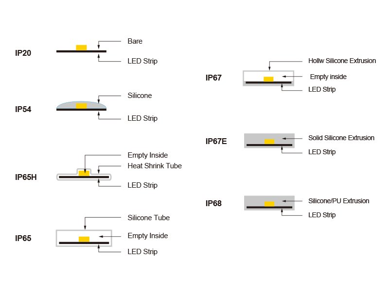
This matters because waterproof LED strips can use different constructions:
- Top-coated silicone with the PCB underside exposed
- Full silicone extrusion
- Silicone tube or sleeve
- Silicone encapsulation extending around the strip
- End caps and cable-entry silicone
If the backing tape is laminated directly to a clean PCB, adhesion may be practical. If the tape must bond to an external silicone surface, a conventional acrylic tape may not be suitable.
Possible solutions include:
- A silicone-compatible PSA
- A supplier-approved primer
- A profile with retaining features
- Mounting clips
- Factory-extruded mechanical geometry
- Brackets or channels
- A hybrid adhesive-plus-mechanical system
Dow’s information on silicone pressure-sensitive adhesives illustrates why silicone-based adhesives are used when wide temperature resistance or adhesion to difficult low-energy surfaces is required.
Do not apply an unknown primer to a silicone waterproof strip without compatibility testing. The primer or solvent can attack, discolor or weaken the encapsulation.
Cause 3: Heat Causes the Adhesive to Creep
LED strip heat does not usually cause an immediate dramatic failure. More often, it gradually changes the mechanical behavior of the adhesive.
As temperature rises, a pressure-sensitive adhesive may become softer. Under continuous load, it can slowly deform. This is known as creep.
Creep is especially important when the strip is:
- Mounted upside down
- Mounted vertically
- Installed at high wattage
- Enclosed without ventilation
- Covered by waterproof encapsulation
- Installed in a small profile
- Mounted on wood, plastic or another poor heat spreader
- Exposed to sunlight
- Installed near ovens, steam rooms or industrial equipment
Three Temperatures Must Be Separated
Application Temperature
The temperature when the tape is installed.
If the tape or substrate is too cold, the adhesive may not wet the surface properly—even if its service-temperature rating is much lower.
Operating Temperature
The stabilized temperature during normal use.
This is influenced by strip wattage, profile, airflow, ambient temperature and duty cycle.
Short-Term Exposure Temperature
A temporary temperature caused by sunlight, commissioning, nearby equipment or another abnormal condition.
A tape may survive a high short-term temperature but perform poorly under a lower continuous load.
Do not select tape using only one maximum-temperature number from a datasheet.
Why More Tape Does Not Solve an Overheating Problem
Replacing a thin tape with a thick foam tape can improve conformity to an uneven surface, but it can also affect:
- Strip-to-profile contact
- Thermal interface thickness
- Profile fit
- LED-to-diffuser distance
- Sidewall clearance
- Heat transfer
This does not mean every foam tape is thermally unsuitable. It means tape thickness and thermal behavior must be evaluated as part of the assembly.
The correct solution to overheating may involve:
- Reducing watts per meter
- Using a larger aluminum profile
- Improving strip-to-profile contact
- Improving ventilation
- Dividing the load
- Changing the waterproof construction
- Reducing ambient temperature
- Using mechanical retention
An LED aluminum profile can spread heat and provide physical protection, but only when its size, installation and surrounding thermal path are appropriate.
Cause 4: Moisture Reaches the Bond Line
A waterproof LED strip can still lose adhesion.
The IP rating of the strip does not automatically establish the water resistance of:
- The backing tape
- The mounting substrate
- The profile finish
- The field-cut end
- The cable entry
- The adhesive edge
- The complete installed assembly
Moisture can reach the bond through:
- Condensation
- Cleaning water
- Capillary action
- Unsealed profile ends
- Rain flowing behind the strip
- Wet mounting surfaces
- High humidity
- Temperature cycling
- Water trapped inside a channel
Condensation Is Often More Dangerous Than Direct Rain
An outdoor strip may survive rainfall but fail when repeated temperature changes create moisture behind it.
Condensation is difficult because it can:
- Form where it is not visible
- Remain trapped between strip and profile
- Contaminate the bond edge
- Promote corrosion
- Repeat through many wet-dry cycles
- Combine with heat and mechanical movement
A dry laboratory peel test does not reproduce this exposure.
For outdoor or wet applications, specify:
- Drainage
- Profile orientation
- End treatment
- Cable-entry direction
- Condensation control
- Adhesive environmental resistance
- Corrosion-compatible materials
- Mechanical backup retention
- A representative environmental test
Cause 5: The Mounting Surface Is Too Rough, Porous or Weak
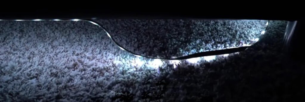
Adhesive tape performs best when it can develop broad, continuous contact.
Difficult substrates include:
- Unfinished wood
- MDF
- Brick
- Concrete
- Textured paint
- Wallpaper
- Fabric
- Dusty plaster
- Rough powder coating
- Uneven stone
- Degraded paint
A highly textured surface reduces real contact area. A porous surface may absorb contamination or contain loose particles. A weak surface layer may detach even when the tape remains perfectly bonded to it.
Why LED Strips Pull Paint Off Walls
When paint comes away with the tape, the failure is not necessarily weak adhesive.
The bond can be stronger than:
- The paint-to-plaster bond
- The plaster surface
- A poorly cured coating
- A contaminated primer
- An aged wallpaper layer
Installing a higher-strength tape may remove an even larger section of the finish.
For drywall, masonry, unfinished wood and similar surfaces, a better approach is often:
- Mechanically fix an aluminum profile.
- Bond the LED strip to the cleaned interior of the profile.
- Use the diffuser and profile to protect the strip.
- Design the profile so it can be serviced later.
The profile transfers structural attachment from an uncertain decorative surface to fasteners selected for the actual wall or substrate.
Cause 6: Insufficient Pressure and Dwell Time
Pressure-sensitive tape requires pressure.
Simply placing the strip onto a profile and running a finger lightly along the LEDs may leave:
- Air pockets
- Incomplete edge contact
- Poor contact near solder joints
- Uneven pressure between components
- Unbonded areas around PCB curvature
Apply controlled, uniform pressure without damaging the LEDs, resistors or solder joints. A suitable roller or flat installation tool can be used when permitted by the strip construction.
Do not press directly onto fragile components with excessive force.
Why Immediate Power-On Can Reduce Reliability
Turning on a high-power strip immediately after mounting adds heat before the adhesive has developed its full bond.
Bond-building time depends on the tape chemistry, temperature and substrate. As one documented example—not a universal rule for all tapes—3M notes that some VHB systems develop progressively higher bond strength over approximately 20 minutes, 24 hours and 72 hours under suitable conditions.
The practical lesson is:
- Do not perform a pull test immediately after installation
- Do not assume immediate handling strength equals final strength
- Allow the tape manufacturer’s specified dwell time
- Avoid full thermal loading during the initial bond-development period where possible
The tesa technical discussion of pressure, dwell time and bonding conditions likewise shows that pressure, surface compatibility and time influence PSA performance.
Cause 7: Cables, Connectors and Corners Pull the Strip Away
A lightweight LED strip can still experience significant localized stress.
Common sources include:
- Heavy lead wires
- Short, rigid cables
- Unsupported connectors
- Cable bundles hanging from strip pads
- A driver cable pulling sideways
- Tight inside corners
- The strip’s natural tendency to straighten
- Repeated movement during maintenance
- Thermal expansion differences
Tape performs poorly when a force continually lifts one edge. This peel or cleavage load can be much more damaging than evenly distributed shear.
Provide Cable Strain Relief
The electrical solder pad should not also function as the mechanical cable support.
Use:
- Cable clips
- Profile end caps with strain relief
- Secured junction points
- Flexible lead transitions
- Appropriate cable length
- Mechanical support near connectors
Secure the cable before it transfers force to the end of the strip.
Do Not Force a Strip Around a Sharp Corner
A flexible PCB bends in its intended direction, but it should not be folded, creased or twisted beyond its specified radius.
At a 90-degree corner, consider:
- Cutting and soldering a flexible lead
- Using a compatible corner connector
- Creating two separate segments
- Using a strip designed for side bending
- Using an appropriate flexible neon construction
The corner method must also preserve current capacity, polarity, waterproofing and serviceability.
Cause 8: The Tape Was Selected by Brand Name Instead of Performance
A branded release liner does not provide a complete adhesive specification.
Even within one manufacturer’s portfolio, tapes differ in:
- Adhesive chemistry
- Carrier construction
- Thickness
- Surface-energy compatibility
- Peel strength
- Static shear performance
- Temperature behavior
- UV resistance
- Moisture resistance
- Plasticizer resistance
- Solvent resistance
- Required primer
- Storage life
- Application-temperature range
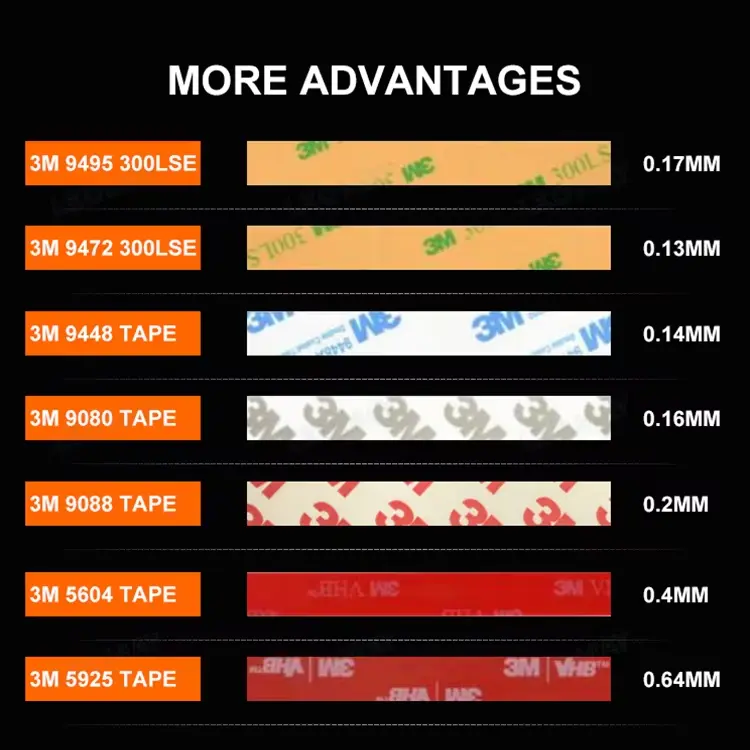
A red liner, printed logo or familiar brand name does not prove that the exact tape is suitable for the strip and project.
The buyer should request:
- Exact tape manufacturer
- Exact tape series or model
- Tape construction
- Total thickness
- Adhesive type
- Applicable datasheet
- Storage conditions
- Production shelf-life control
- Substrate compatibility
- Relevant environmental test data
Substitution should require approval when the tape is part of the accepted product specification.
LED Strip Tape Selection by Mounting Surface
The following matrix is a starting point, not a substitute for testing.
| Mounting surface | Main risk | Typical approach |
| Clean anodized aluminum | Oil, machining residue or finish variation | Compatible acrylic transfer tape; verify actual profile finish |
| Raw aluminum | Oil and oxidation | Clean and stabilize surface; validate corrosion and adhesion |
| Powder-coated metal | Variable surface energy and texture | Test exact coating; consider LSE-compatible tape or approved primer |
| Painted metal | Paint adhesion and cure condition | Confirm paint compatibility and paint-to-metal strength |
| Glass | Moisture at bond edge | Clean carefully; consider moisture exposure and approved surface treatment |
| Ceramic tile | Cleaner residue and joints | Bond only to clean, smooth tile; avoid relying on grout |
| Acrylic or polycarbonate | Coating, stress cracking and solvent sensitivity | Use compatible cleaner and tape; test for chemical interaction |
| Polyethylene or polypropylene | Low surface energy | LSE-specific tape, approved primer or mechanical profile |
| Plasticized PVC | Plasticizer migration | Use compatible tape or barrier system; perform aging test |
| Silicone | Very low surface energy | Silicone-compatible PSA or mechanical retention |
| Rubber or EPDM | Oils, plasticizers and low surface energy | Specialized tape/primer or mechanical retention |
| Finished wood | Finish variability and movement | Test actual finish; profile generally preferred |
| Unfinished wood or MDF | Porosity, dust and fibers | Seal surface or mechanically mount a profile |
| Painted drywall | Weak paint or plaster layer | Mechanically mount a profile |
| Concrete, brick or stone | Roughness, dust and moisture | Mechanical profile mounting |
| Outdoor façade | UV, water, heat and wind load | Mechanically fixed profile with environmental validation |
Tape Is Not Always the Correct Primary Mounting Method
Backing tape is extremely useful for:
- Positioning the strip
- Maintaining PCB contact with a profile
- Simplifying assembly
- Preventing movement before the diffuser is installed
- Supporting low-power indoor installations
It should not automatically be treated as the sole structural attachment for:
- Overhead public installations
- High-temperature projects
- Saunas
- Outdoor façades
- Wet or immersed installations
- Rough masonry
- High-vibration equipment
- Full silicone extrusion
- Heavy cables or connectors
- Safety-critical locations
- Surfaces with unknown coatings
- Installations where falling components create risk
In these cases, consider a hybrid system:
Adhesive for positioning and thermal contact + profile, clip or fastener for mechanical retention
This approach prevents one adhesive interface from becoming the only barrier between normal operation and complete detachment.
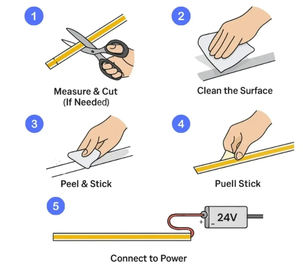
A Professional LED Strip Installation Procedure
1. Approve the Complete Assembly
Confirm:
- LED strip model
- Tape model
- Mounting substrate
- Surface finish
- Aluminum profile
- Strip wattage
- Expected operating temperature
- Environmental exposure
- Cable and connector arrangement
- Mechanical-retention method
Testing a tape on stainless steel does not prove its performance on the project’s powder-coated profile.
2. Inspect the Materials
Check for:
- Expired or poorly stored tape
- Damaged release liner
- PCB curvature
- Contaminated strip backing
- Oil inside the profile
- Moisture
- Uncured paint
- Loose powder coating
- Rough extrusion marks
3. Dry-Fit Before Removing the Liner
Verify:
- Strip width
- Profile inner width
- Connector clearance
- Cable exit
- Cut position
- Corner geometry
- Feed direction
- Diffuser clearance
The internal width of the profile should allow practical installation without forcing or damaging the strip. Xmart recommends confirming the strip width, profile width, adhesive surface and thermal path before sampling, particularly for ultra-narrow LED strip installations.
4. Prepare the Surface
Use the approved cleaning and preparation process for the actual substrate.
The surface should be:
- Structurally stable
- Clean
- Dry
- Free of loose particles
- Within the tape’s application-temperature range
5. Install Without Stretching the Strip
Do not stretch the PCB or backing tape during application.
Stretching creates residual stress that can later pull the strip back from ends and corners.
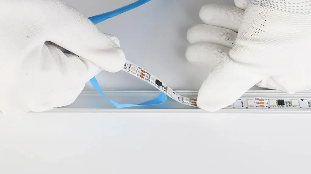
Align a short section first, then progressively remove the release liner while positioning the strip.
6. Apply Uniform Pressure
Use sufficient pressure to create full contact while protecting LEDs and components.
Pay special attention to:
- Strip ends
- Areas beside solder joints
- Corners
- Cable exits
- PCB splices
- Sections that initially curl upward
7. Secure Cables and Connectors
Provide strain relief before leaving the strip unsupported.
8. Allow Bond Development
Follow the tape manufacturer’s specified dwell time and environmental conditions before applying full thermal or mechanical load.
9. Commission at Operating Temperature
After the bond has developed:
- Operate the strip at maximum intended power
- Allow temperature to stabilize
- Inspect the edges
- Check vertical or overhead movement
- Inspect connectors
- Measure the relevant temperature point
- Repeat at worst-case ambient conditions when practical
How to Test LED Strip Adhesion Before Mass Production
A five-minute hand-peel test is useful for screening, but it cannot predict long-term project performance.
A more useful validation plan includes the following tests.
Initial Adhesion Test
Purpose:
- Confirm surface preparation
- Identify obvious incompatibility
- Compare application methods
Control:
- Substrate
- Cleaning method
- Pressure
- Temperature
- Dwell time
- Sample width and length
Peel Test
Purpose:
- Compare resistance to edge lifting
- Identify the failed interface
Record:
- Peel angle
- Speed
- Dwell time
- Temperature
- Substrate
- Failure mode
A peel value obtained on stainless steel should not be treated as the value for painted wood, silicone or powder-coated aluminum.
Static Shear Test
Purpose:
- Evaluate long-term holding under vertical or overhead load
- Detect temperature-related creep
Test at:
- Room temperature
- Expected operating temperature
- Worst-case ambient temperature
Thermal Soak Test
Operate the complete strip-profile assembly at the maximum intended power until temperature stabilizes.
Inspect:
- Edge lifting
- Adhesive displacement
- Strip movement
- PCB discoloration
- Connector temperature
- Profile temperature
Thermal-Cycling Test
Cycle the assembly between representative low and high temperatures.
This can reveal:
- Differential expansion
- Edge lifting
- Moisture pumping
- PCB movement
- Progressive adhesive fatigue
Humidity or Condensation Test
For damp and outdoor applications, test the actual assembly—not only the tape.
Include:
- Profile
- Strip
- End treatment
- Cable entry
- Surface finish
- Mechanical support
Material-Compatibility Aging
This is important for:
- Silicone
- Rubber
- Flexible PVC
- Paint
- Sealants
- Cleaners
- Primers
- Waterproof encapsulation
Inspect for:
- Softening
- Swelling
- Discoloration
- Residue
- Reduced peel strength
- Loss of elasticity
Full-Length Trial Installation
Short coupons may not reveal:
- PCB curl
- Cable stress
- Reel-memory effects
- Long ceiling runs
- Repeated corners
- Installer variation
- Local hot spots
For significant projects, install a representative full-length section and operate it under realistic conditions before approving mass production.
Adhesion Requirements for an LED Strip RFQ
Include the following information in the product specification.
Tape Specification
- Tape manufacturer
- Exact tape model
- Adhesive chemistry
- Tape thickness
- Carrier type
- Release-liner type
- Storage and shelf-life requirements
- Approved alternatives
- Substitution-control procedure
Substrate Specification
- Base material
- Surface finish
- Surface-energy category where known
- Roughness or texture
- Cleaning process
- Primer or surface treatment
- Minimum application temperature
Environmental Specification
- Maximum ambient temperature
- Expected stabilized strip temperature
- Humidity
- Condensation
- UV exposure
- Water exposure
- Cleaning chemicals
- Oils or solvents
- Salt or chlorine
- Vibration
Mechanical Specification
- Mounting orientation
- Maximum segment length
- Cable strain relief
- Corner method
- Mechanical backup
- Minimum dwell time
- Required pressure method
- Service and replacement process
Acceptance Evidence
- Tape datasheet
- Tape traceability
- Substrate compatibility test
- Thermal test
- Peel or shear comparison
- Environmental-aging result
- Approved assembly sample
- Production inspection method
Common Adhesive Fixes That Do Not Work
“Use More Adhesive”
A thicker tape does not repair weak paint, trapped moisture or an overheating strip.
“Add Super Glue at the Ends”
Cyanoacrylate and other unapproved adhesives can:
- Become brittle
- Damage plastics
- Produce visible blooming
- Prevent service
- Attack waterproof materials
- Concentrate stress at the strip end
Any secondary adhesive should be evaluated for material compatibility, temperature and serviceability.
“Use Hot-Melt Glue”
Hot-melt adhesive can soften when the strip operates at elevated temperature. Its adhesion and aging depend on the exact formulation and substrate.
It should not be assumed to provide permanent engineering retention.
“Install It While the Profile Is Still Wet”
Moisture or cleaner trapped under the tape can prevent proper wet-out and later initiate edge failure.
“The Strip Is IP67, So the Tape Is Waterproof”
The strip’s IP classification does not automatically include adhesion to the project substrate.
“The Aluminum Profile Will Keep Everything Cool”
A profile helps only when the strip makes suitable contact and the profile can release heat to its surroundings.
“If It Sticks Today, It Is Approved”
Immediate tack does not establish performance after heat, moisture, load and aging.
Frequently Asked Questions
Why do my LED light strips keep falling off?
The most common causes are contamination, low-surface-energy materials, insufficient pressure, immediate loading, excessive operating temperature and cable or corner stress. Inspect where the tape remained after failure to identify the likely interface.
Can LED strips be attached directly to painted walls?
They can stick initially, but the long-term bond is limited by the paint and wall surface. The tape may remove paint or plaster during service or replacement. A mechanically attached aluminum profile is more reliable for permanent installations.
What is the best adhesive tape for LED strips?
There is no universal best tape. The correct tape depends on the strip backing, substrate, temperature, moisture, mounting orientation and required service life. Select an exact tape grade and test it on the real assembly.
Is 3M tape always suitable for LED strips?
3M manufactures many different tape families. A branded liner alone does not identify the performance of the exact product or prove suitability. Request the tape model and datasheet.
Can I apply new tape over the old LED strip tape?
Not for a controlled installation. Old adhesive creates an uncertain surface and may already be contaminated or thermally degraded. Remove the existing adhesive using a material-compatible process and validate the new bond.
Does heat make LED strip adhesive fail?
It can. Higher temperature can soften the adhesive, reduce shear resistance and accelerate creep. Overheating may also indicate that the strip lacks an adequate thermal path.
Should waterproof LED strips use backing tape?
It depends on their construction. Top-coated strips may retain an exposed PCB underside suitable for tape, while fully extruded silicone or sleeved products may require specialized adhesive or mechanical mounting.
How long should I wait before turning on the LED strip?
Follow the specific tape manufacturer’s dwell-time instructions. Some pressure-sensitive adhesives continue building strength for many hours after application. For demanding projects, avoid immediate full-power thermal loading.
Are mounting clips better than adhesive?
They perform different functions. Tape provides continuous positioning and surface contact; clips provide mechanical retention. High-risk applications often benefit from using both.
Can adhesive tape replace an aluminum profile?
Usually not when the project requires heat spreading, optical diffusion, impact protection or long-term mechanical retention. The tape and profile perform different functions.
The Most Reliable Solution Is a Designed Mounting System
LED strip adhesive should be selected at the same time as the:
- PCB construction
- Strip wattage
- Waterproof method
- Aluminum profile
- Mounting surface
- Driver
- Cable
- Connector
- Environmental protection
Changing any one of these can change the adhesive requirement.
For custom projects, Xmart Lighting can coordinate the strip dimensions, backing-tape requirement, waterproof construction, cable exit and profile-compatible installation during sample development.
When requesting a quotation, provide:
- A photograph or sample of the mounting surface
- Substrate and finish
- Installation orientation
- Profile drawing
- Strip wattage
- Maximum ambient temperature
- Moisture or chemical exposure
- Segment lengths
- Cable direction
- Required service life
- Whether mechanical retention is permitted
Submit these details through the Xmart Lighting quick quote form and request an assembly-level sample when adhesion is a critical project requirement.