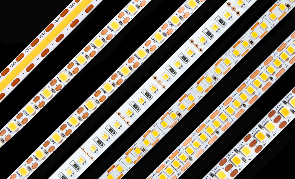
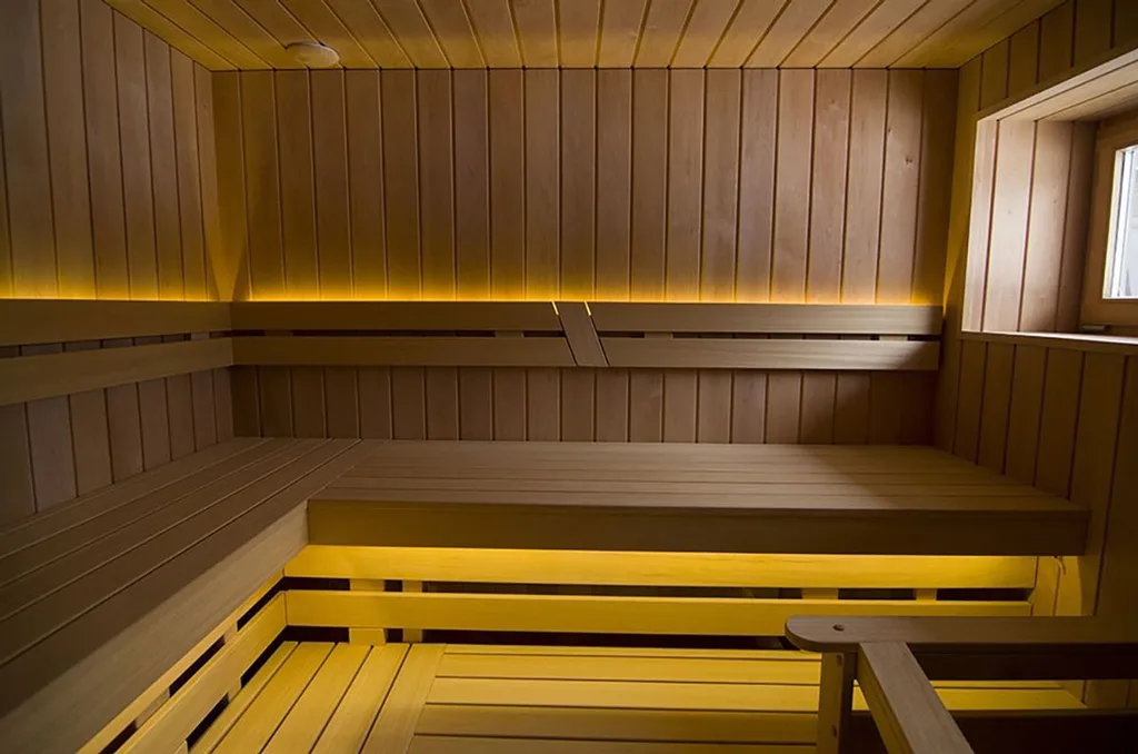
A standard waterproof LED strip is not automatically suitable for a sauna or steam room.
Saunas expose lighting products to high ambient temperatures, strong temperature gradients and radiant heat from the heater. Steam rooms usually operate at lower air temperatures but expose products to near-saturated humidity, condensation, cleaning chemicals and repeated wet-dry cycles.
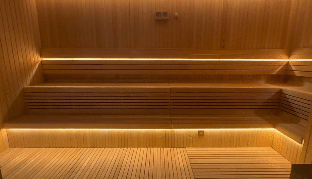
These environments stress different parts of an LED strip system:
- LED packages
- Flexible PCB
- Resistors and current regulators
- Solder joints
- Silicone encapsulation
- Cable jackets
- End seals
- Connectors
- Adhesive
- Aluminum profiles
- LED drivers and controllers
The correct specification must therefore define both temperature and moisture exposure at the exact installation position.
Do not specify only:
24V IP68 LED strip for sauna.
A professional specification should state:
Maximum measured ambient and surface temperature, heater distance, humidity and condensation exposure, LED package and drive current, silicone construction, IP requirement, cable and end-seal construction, driver location, circuit length and validation method.
Quick Answer
For most sauna and steam-room projects:
- Use a purpose-designed high-temperature LED strip.
- Prefer an isolated low-voltage DC system where required or appropriate.
- Keep the LED driver and controller outside the high-temperature, high-humidity enclosure unless the exact equipment is specifically rated and permitted for that location.
- Map actual temperatures before selecting the strip.
- Keep lighting away from the heater’s severe radiant-heat zone.
- Use high-temperature LED packages operated below their maximum current.
- Select silicone, cables, seals and connectors for the full temperature and moisture exposure.
- Do not rely on the adhesive tape as the only mounting method.
- Use factory-finished lengths for demanding wet installations.
- Verify the complete strip assembly—not only the LED’s LM-80 report.
For dry saunas, temperature is usually the primary challenge.
For steam rooms, condensation, sealing and material compatibility may be more important than maximum air temperature.
Sauna and Steam Room Are Not the Same Environment
Treating both spaces as “hot and wet” leads to poor specifications.
| Environmental factor | Traditional dry sauna | Infrared sauna | Steam room |
|---|---|---|---|
| Air temperature | High | Moderate | Lower than a traditional sauna |
| Humidity | Normally lower, with temporary peaks | Usually moderate | Very high or near saturation |
| Radiant heat | Severe near heater | Significant near emitters | Usually less severe |
| Condensation | Intermittent | Possible | Continuous or frequent |
| Water exposure | Cleaning, splash and steam events | Cleaning and perspiration | Condensation, cleaning and possible water jets |
| Main LED risk | Temperature and thermal cycling | Radiant heating | Moisture, seal failure and corrosion |
| Main material risk | Hardening, discoloration, solder and cable aging | Local hot spots | Swelling, delamination, corrosion and chemical exposure |
| Preferred validation | Temperature mapping and high-temperature operation | Radiant-heat and local-temperature test | Humidity, condensation, sealing and chemical test |
Project terminology can vary. A “steam sauna” should be specified according to its actual temperature, humidity and water exposure—not its marketing name.
Start with a Temperature Map, Not a Product Datasheet
The air temperature shown on the sauna controller does not tell you the temperature at every lighting position.
Hot air rises, creating a vertical temperature gradient. The temperature close to the ceiling may be much higher than under a bench. A strip near the heater can also receive radiant heat and become hotter than the surrounding air.
Before product selection, record temperatures at:
- Ceiling
- Upper wall
- Lower wall
- Under the bench
- Behind the backrest
- Inside the proposed lighting recess
- Near the heater
- Cable-entry point
- Driver service area
- Aluminum-profile surface
Measure during:
- Initial heating
- Normal occupied operating temperature
- Maximum thermostat setting
- Water application to sauna stones where relevant
- Extended steady-state operation
- Cooling
- Repeated heating cycles
The Hottest Air Temperature May Not Be the Hottest Product Temperature
A strip may be affected by:
- Radiant energy from the heater
- Heat trapped inside a wooden recess
- Insulation behind the mounting surface
- Poor airflow
- Dark mounting materials
- Other electrical equipment
- A small enclosed profile
Conversely, a strip under a lower bench may experience a substantially less severe temperature than a ceiling-mounted strip.
The result should be a position-specific thermal schedule.
| Lighting position | Maximum measured ambient | Maximum mounting-surface temperature | Radiant exposure | Moisture exposure |
| Under upper bench | Low/medium | Cleaning and condensation | ||
| Behind backrest | Medium | Humidity | ||
| Upper wall | Medium/high | Humidity | ||
| Ceiling perimeter | High | Heat and steam | ||
| Near heater | Severe | Heat and thermal cycling |
Do not use a product rated to 100°C in a location that measures 100°C. The LEDs and onboard components will operate above ambient, leaving no meaningful thermal margin.
The LED Package Matters—But It Is Not the Whole Strip
A high-temperature LED strip should begin with an LED package designed and characterized for elevated-temperature operation.
The LED specification should include:
- Exact LED manufacturer and series
- Maximum junction temperature
- Recommended operating range
- Thermal resistance
- Drive current
- LM-80 test conditions
- Lumen maintenance at relevant temperature
- Chromaticity maintenance
- Forward-voltage behavior
- Sulfur or chemical resistance where relevant
Ambient Temperature Is Not LED Junction Temperature
The LED junction is the internal light-generating region of the semiconductor.
Its temperature is higher than the measured PCB or surrounding air temperature.
A simplified relationship is:
LED junction temperature ≈ measured reference temperature + thermal resistance × LED electrical power
The exact calculation must use the LED manufacturer’s specified thermal path and measurement point.
Lumileds’ LED thermal-measurement guidance explains why junction temperature is calculated from an accessible reference temperature, thermal resistance and electrical power rather than measured directly with a basic surface thermometer.
Example
Assume:
- Sauna air at the strip: 85°C
- PCB and LED reference point after stabilization: 92°C
- Estimated junction rise above that reference: 12°C
Estimated junction temperature:
92°C + 12°C = 104°C
The LED package must be evaluated at the estimated junction temperature—not only at the 85°C room temperature.
The PCB, resistors, solder, silicone and cables must also tolerate their own local temperatures.
Lower Drive Current Creates Thermal Margin
Driving an LED below its maximum current can:
- Reduce junction-temperature rise
- Improve efficacy
- Reduce thermal droop
- Improve lumen maintenance
- Reduce stress on phosphor and package materials
A sauna strip should not simply use a standard LED circuit inside a higher-temperature jacket.
A better design may use:
- More LED packages per meter
- Lower current per LED
- Lower watts per meter
- Wider PCB
- Improved copper layout
- High-temperature components
- Thermal derating
More LEDs per meter do not necessarily mean more heat if the total wattage remains controlled.
High Maximum Junction Temperature Does Not Mean High Ambient Rating
Suppose an LED package has a high maximum junction-temperature limit.
That does not mean the completed strip can operate at the same ambient temperature because the system also contains:
- Flexible PCB
- Solder
- Resistors
- Current-control components
- Adhesive
- Cable
- Silicone
- Connector
- End seal
The lowest-rated critical component can determine the actual product limit.
LM-80 Does Not Prove Sauna Strip Lifetime
LM-80 data can help evaluate light-output and color maintenance of LED packages, arrays or modules under defined conditions.
It does not prove the lifetime of the complete sauna strip.
A strip can fail before the LED package because of:
- Cracked solder joints
- PCB warping
- Resistor drift
- Current-regulator failure
- Silicone discoloration
- Cable-jacket hardening
- End-seal separation
- Connector corrosion
- Adhesive failure
- Driver failure
The Illuminating Engineering Society states that LM-80 and TM-21 should not be used as the sole basis for complete-product lifetime claims. See the IES position on LED product lifetime.
If a supplier claims 50,000 or 60,000 hours in a sauna, request:
- LED LM-80 report
- TM-21 calculation, where applicable
- LED test temperature
- Actual strip operating temperature
- Complete-strip high-temperature test
- Test duration
- Number of samples
- Failure definition
- Lumen and color change
- Warranty temperature conditions
What Makes a High-Temperature LED Strip Different?
A genuine sauna strip should be engineered as a complete high-temperature assembly.
1. High-Temperature LED Packages
The LED platform should provide:
- Documented elevated-temperature performance
- Suitable thermal resistance
- Stable package materials
- Controlled drive current
- Appropriate lumen and color maintenance
Xmart’s sauna-room LED strip platform includes single-color configurations based on a high-temperature SMD3030 architecture and separate RGBW and neon-flex options.
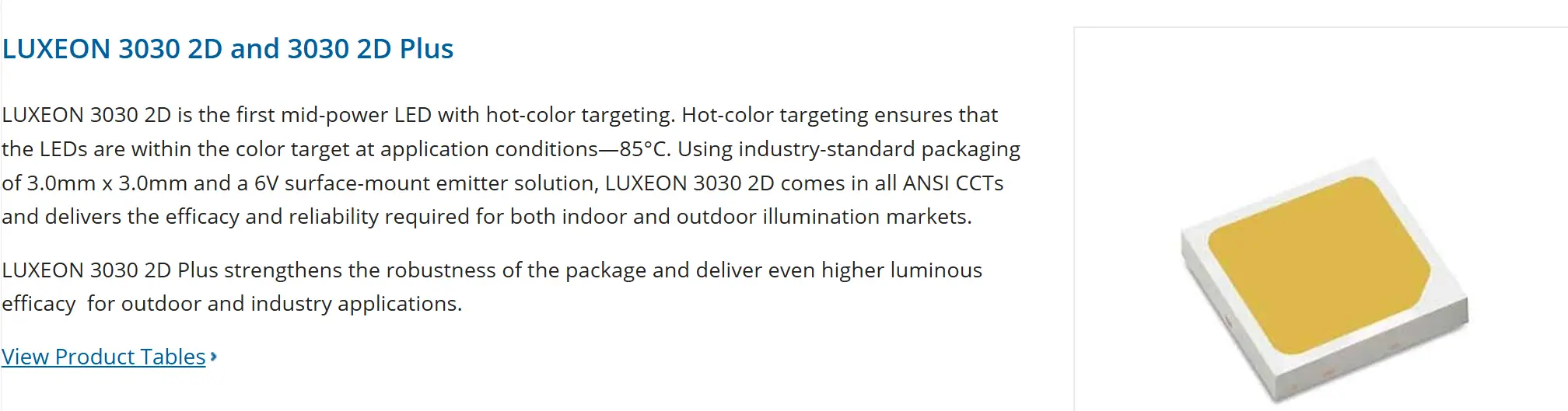
The relevant datasheet and test report should still be matched to the exact offered model, wattage and installation temperature.
2. Thermally Suitable Flexible PCB
The PCB must carry current and maintain mechanical stability at the declared temperature.
Specify:
- PCB width
- Copper construction
- Maximum W/m
- Maximum circuit current
- Solder-mask temperature suitability
- Maximum continuous run
- Feed arrangement
- Allowed bending radius
A narrow PCB can concentrate heat and increase voltage drop.
3. High-Temperature Solder and Components
LED strips contain many repeated solder joints.
Thermal cycling can create stress because:
- Copper expands
- PCB materials expand
- LED packages expand
- Silicone expands
- Solder joints constrain movement
The design should be tested over repeated heating and cooling cycles, not only held at one constant temperature.
4. Suitable Cable and Connector Materials
Ordinary cable can harden, deform or lose insulation performance in a high-temperature cavity.
Specify:
- Conductor size
- Insulation material
- Temperature rating
- Moisture rating
- Cable length
- Cable exit direction
- Strain relief
- Connector temperature rating
- Seal compatibility
The cable inside the sauna wall may also pass through insulation that traps heat.
Silicone: Necessary Protection, but Not a Universal Answer
Silicone is often used for sauna and steam-room strips because suitable formulations can provide:
- High-temperature flexibility
- Moisture protection
- Electrical insulation
- Optical transmission
- Resistance to thermal cycling
- A soft, impact-resistant exterior
But the word “silicone” does not define performance.
Silicone formulations differ in:
- Temperature capability
- Hardness
- Tear strength
- Optical clarity
- Yellowing resistance
- Adhesion
- Cure chemistry
- Volatile content
- Chemical resistance
- Water-vapor permeability
- Flame behavior
Food-Grade Silicone Is Not the Same as Electrical Approval

“Food-grade” may describe suitability under a particular food-contact framework. It does not automatically establish:
- Electrical insulation
- Flame resistance
- High-temperature optical stability
- Chlorine resistance
- Steam-room suitability
- Long-term adhesion
- Complete-product safety
Request the material designation and the test evidence relevant to the lighting application.
Branded Silicone Does Not Prove the Complete Assembly
A strip using a recognized silicone brand can still fail because of:
- Incorrect mixing
- Incomplete curing
- Contamination
- Voids
- Poor adhesion to the cable
- Insufficient wall thickness
- Incompatible end-seal material
- Process variation
Material selection and manufacturing control are both important.
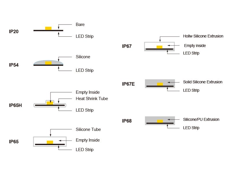
Silicone Tube, Extrusion or Potting?
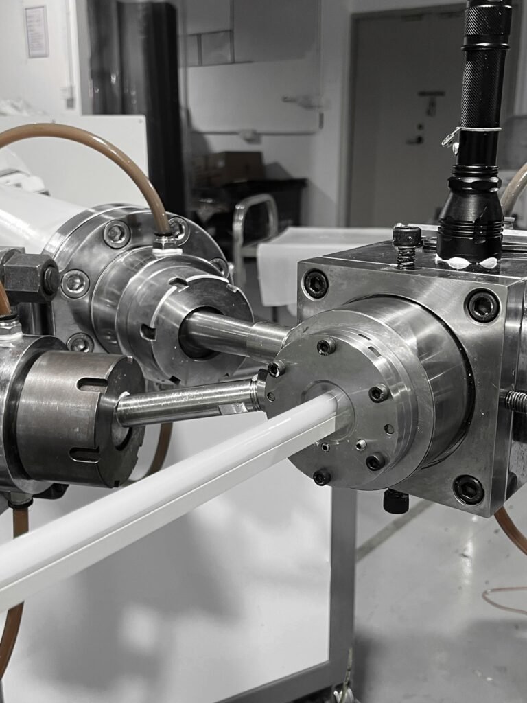
Different waterproof constructions behave differently.
Silicone Top Coating
Potential benefits:
- Smaller dimensions
- Better heat release than full encapsulation
- Easier cutting and soldering
Limitations:
- PCB underside and edges may remain vulnerable
- Less suitable for continuous condensation
- Field joints require careful sealing
Silicone Tube
Potential benefits:
- Physical separation between strip and exterior
- Flexible replacement of the internal strip
- Useful moisture protection in appropriate designs
Limitations:
- Air gaps can affect heat transfer
- Water can migrate along the tube if an end fails
- End caps remain critical
- The internal strip can move
Solid Silicone Extrusion
Potential benefits:
- Continuous outer construction
- Good flexibility
- Strong environmental protection
- Suitable for dotless neon-style lighting
Limitations:
- Greater thermal insulation
- More difficult field repair
- Cut ends require a controlled sealing process
- Optical and dimensional change at high temperature must be tested
Full Potting or Injection
Potential benefits:
- Strong sealing
- Reduced internal voids when processed correctly
Limitations:
- Heat retention
- Material stress during thermal cycling
- Difficult repair
- Potential yellowing or hardness change
The best construction depends on whether the dominant stress is heat, condensation, cleaning water or direct viewing.
IP Rating Is Not a Temperature Rating
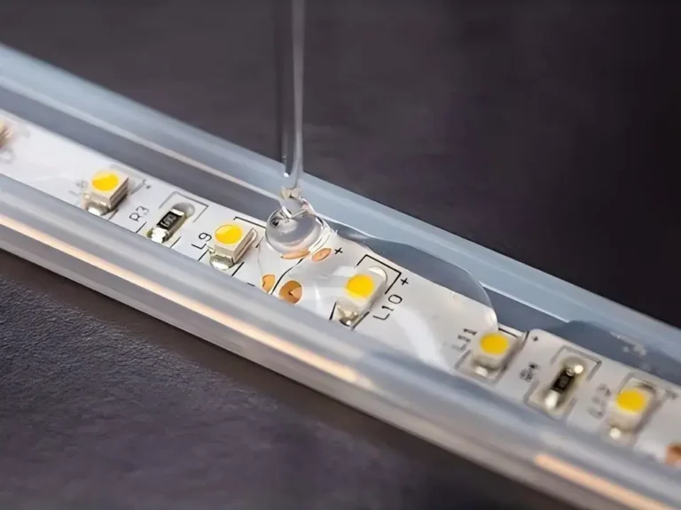
An IP rating measures protection against specified solid-object and water-ingress conditions.
It does not determine:
- Maximum operating temperature
- Steam resistance
- Condensation resistance
- Silicone yellowing
- Thermal cycling
- Cleaning-chemical resistance
- Cable-jacket durability
- Long-term seal life
An IP68 strip can pass an immersion test at room temperature and fail after repeated exposure to sauna heat.
Dry Sauna IP Selection
A dry sauna may not need the same immersion protection as a steam room, but moisture can still come from:
- Steam bursts
- Cleaning
- Perspiration
- Condensation during cooling
- Water applied to the heater stones
The required IP level should follow the installation zone and applicable regulations.
Steam Room IP Selection
A steam room may expose the strip to:
- Continuous high humidity
- Condensation on every surface
- Water running behind profiles
- Cleaning water
- Detergents and disinfectants
- Repeated warm-wet and cool-dry cycles
A higher IP classification can be appropriate, but IP68 alone does not prove steam-room durability.
Request evidence for:
- High-temperature humidity
- Condensation cycling
- Cable entries
- Factory end seals
- Cleaning chemicals
- Post-aging ingress protection
IP67 and IP68 Do Not Automatically Include Water-Jet Resistance
Immersion and water-jet tests represent different exposures.
If the room is cleaned with a hose or pressure spray, specify the applicable water-jet requirement separately.
Steam Can Be Harder to Control Than Liquid Water
A product that survives brief immersion may still experience problems in saturated warm air.
Steam and condensation can:
- Reach small interfaces
- Condense inside cooler cavities
- Remain behind profiles
- Carry cleaning residues
- Create repeated pressure and temperature changes
- Promote corrosion at cut ends
- Attack adhesive bonds
The installation should allow:
- Drainage
- Inspection
- Replacement
- Drying where possible
- No concealed water traps
- Properly oriented cable entries
Driver Location: Keep the Most Temperature-Sensitive Component Outside
The LED driver is often one of the most temperature-sensitive parts of the system.
A driver mounted inside a hot sauna may experience:
- Reduced output capacity
- Shortened capacitor life
- Thermal shutdown
- Unstable dimming
- Premature component failure
- Increased fire risk
The default professional design should place the driver outside the sauna or steam-room enclosure in an accessible, ventilated and code-compliant service location.
The controller, decoder and receiver should normally be treated similarly unless specifically rated and permitted for the installation zone.
“Outside” Must Still Be Defined Properly
A driver placed outside the visible cabin can still be exposed to heat if it is installed:
- Above an insulated ceiling
- Inside a sealed wall cavity
- Beside the heater flue
- In a small unventilated box
- Above a steam generator
- In a humid service void
Record:
- Maximum driver ambient temperature
- Ventilation
- Enclosure
- Driver derating curve
- Required clearances
- Maintenance access
- Distance to the strip
Driver Derating
An LED driver may deliver its full rated power only below a specified ambient temperature.
At higher temperatures, its permitted load may decrease.
Do not size the driver using only:
Strip watts × length + generic 20%
Verify:
- Actual maximum strip power
- Driver loading requirement
- Ambient derating
- Enclosure derating
- Cable losses
- Dimming method
- Minimum load
- Inrush current
- Local electrical requirements
Low-Voltage DC Is Usually the Practical Architecture
A 24V constant-voltage strip is commonly used because it offers:
- Lower current than 12V at the same power
- Broad driver availability
- Practical control options
- Relatively manageable cut units
- Separation of the driver from the hot room
However, low voltage does not eliminate the need for:
- Appropriate electrical isolation
- Circuit protection
- Correct cable size
- Moisture-resistant connections
- RCD/GFCI protection where required
- Compliance with local installation rules
High-voltage AC strips should not be substituted merely to avoid voltage drop inside an occupied sauna or steam room.
Moving the Driver Outside Creates a Voltage-Drop Problem
The external driver may be several meters from the LED strip.
For a two-conductor DC circuit:
Cable voltage drop = 2 × one-way cable length × current × conductor resistance per unit length
Long cable runs can cause:
- Lower strip voltage
- Reduced brightness
- End-to-end variation
- RGBW color-mixing errors
- Unstable operation
- Lower actual power
Possible solutions include:
- Larger cable conductors
- Shorter branches
- Multiple home-run cables
- Center feeding
- Feeding from both ends where validated
- Moving the driver to a cooler but closer service location
- Using 48V where the product and local rules permit
- Reducing W/m
Do not increase the driver output voltage without confirming the maximum voltage permitted at the strip input.
Place the Light in the Least Severe Useful Location
Sauna lighting should be designed around heat zones.
Potentially less severe locations include:
- Under benches
- Behind lower backrests
- Beneath handrails
- Low wall coves
- External perimeter details
Potentially more severe locations include:
- Ceiling
- High wall
- Directly above the heater
- Beside heater stones
- Enclosed upper recesses
- Locations exposed to direct radiant heat
A strip capable of operating in one sauna position is not automatically approved for every position.
IEC 60364-7-703 addresses special electrical-installation requirements for rooms and cabins containing sauna heaters, including temperature distribution and protection against electric shock. See IEC 60364-7-703.
The project’s electrical designer should establish the applicable sauna zones and equipment requirements. Do not use a universal internet distance from the heater as a substitute for the heater instructions, product rating and local code.
An Aluminum Profile Cannot Cool Below the Sauna Temperature
Aluminum profiles are useful for:
- Heat spreading
- Mechanical protection
- Straight installation
- Diffuser support
- Cable management
But an aluminum profile is not a refrigeration system.
If the surrounding air and mounting surface are already extremely hot, the profile cannot cool the strip below that environment. It can only distribute heat and improve transfer to its surroundings.
In a sauna, also consider:
- Profile surface temperature
- User touch
- Expansion
- Corrosion
- Fastener compatibility
- Water trapping
- Timber movement
- Diffuser temperature rating
A recessed profile inside insulating timber may release heat poorly.
Do Not Depend on Backing Tape Alone
Heat, humidity and timber movement can weaken pressure-sensitive adhesive.
Possible failure modes include:
- Adhesive creep
- Edge lifting
- Strip movement
- Complete detachment
- Loss of thermal contact
- Contamination from wood oils or finishes
Use an installation system that can include:
- High-temperature-compatible profile
- Mechanical clips
- Retaining features
- Suitable fasteners
- Factory mounting
- Replaceable channels
The adhesive may help position the strip inside a profile, but it should not necessarily be the only component preventing an overhead strip from falling.
White, RGBW or Neon Flex?
The correct light source depends on the design effect and operating stress.
Single-Color White LED Strip
Usually best for:
- Traditional warm ambient lighting
- Indirect bench lighting
- Simple dimming
- Higher efficacy
- Lower system complexity
Common sauna CCT choices include:
- 2200K
- 2400K
- 2700K
- 3000K
Very warm light often complements timber finishes, but final selection should be approved inside the actual sauna materials.
RGBW LED Strip
Suitable for:
- Wellness scenes
- Chromotherapy concepts
- Premium spa controls
- Dynamic mood lighting
It adds complexity:
- More conductors
- More heat per meter at maximum output
- Controller location
- Color-mixing variation
- More complicated cable sealing
- Different power at different channel combinations
Specify the worst-case permitted channel state. “RGBW 19.2 W/m” is incomplete unless it states whether all channels may operate at full output simultaneously.
Sauna LED Neon Flex
Useful for:
- Direct-view lines
- Curves
- Dotless architectural details
- Integrated backrests
- Decorative outlines
It also introduces:
- Thicker silicone
- More thermal insulation
- A larger bending radius
- Specific cutting and sealing methods
- Greater importance of factory-finished lengths
Xmart’s sauna range includes single-color SMD3030 strip, RGBW strip and silicone sauna LED neon flex. Selection should follow the installation temperature, visual effect, circuit design and sealing requirement.
Factory-Finished Lengths Are Preferable
Every field cut creates a new potential failure point.
A cut can expose:
- Copper pads
- PCB edges
- Capillary paths
- Silicone interfaces
- Solder joints
In a steam room, a hand-sealed cut end may be exposed to continuous condensation and cleaning.
For higher-risk projects, specify:
- Factory-cut lengths
- Factory-soldered cables
- Molded or injected end seals
- Controlled sealant cure
- Cable pull testing
- Leak or ingress testing
- Batch traceability
If field cutting is permitted, require a validated process with:
- Approved sealant
- Surface-preparation method
- Cure time
- Application temperature
- End cap
- Inspection
- Electrical test
- Responsibility for the resulting IP classification
Common Failure Modes
LEDs Become Dim or Change Color
Possible causes:
- High junction temperature
- Excessive drive current
- Phosphor aging
- Thermal droop
- Moisture or chemical exposure
Sections Fail Intermittently
Possible causes:
- Cracked solder joints
- PCB thermal fatigue
- Connector movement
- Cable-entry stress
- Condensation
Silicone Yellows
Possible causes:
- Unsuitable formulation
- High temperature
- UV from adjacent glazing
- Cleaning chemicals
- Incomplete cure
- Material contamination
Strip Detaches
Possible causes:
- Adhesive creep
- Wood surface contamination
- Heat
- Humidity
- No mechanical retention
End of Run Is Dim
Possible causes:
- Long driver-to-strip cable
- Undersized conductors
- PCB voltage drop
- Excessive branch length
- Connector resistance
Driver Fails Prematurely
Possible causes:
- Installed inside the sauna
- Hot service cavity
- No ventilation
- Incorrect derating
- Condensation
- Overloading
IP-Rated Strip Develops Corrosion
Possible causes:
- Field-cut end
- Failed cable entry
- Condensation after thermal cycling
- Chemical cleaner
- Incompatible sealant
- Damaged silicone
A Professional Validation Plan
1. Baseline Inspection
Record:
- Product model and revision
- LED model
- Strip dimensions
- Cable construction
- Seal construction
- Power
- Light output
- CCT and chromaticity
- Photographs
- Insulation and electrical results
2. Maximum-Temperature Operating Test
Test the complete strip at:
- Maximum declared ambient
- Maximum rated voltage
- Maximum permitted power
- Intended profile
- Intended mounting orientation
- Maximum branch length
Measure:
- Hottest LED reference point
- PCB
- Resistor or regulator
- Connector
- Cable entry
- Profile
- Light output
- Power
- Color
3. Thermal Cycling
Cycle between representative room temperature and maximum sauna temperature.
Inspect for:
- Cracking
- Delamination
- PCB warping
- Seal movement
- Solder failure
- Cable hardening
- Color shift
4. High-Humidity and Condensation Test
For steam-room products, test repeated warm-humid and cool-condensing conditions.
Inspect:
- End seals
- Cable entries
- Internal fogging
- Electrical leakage
- Corrosion
- Adhesion
- Optical change
5. Chemical-Cleaning Test
Use the actual cleaning product, dilution, contact time, temperature and rinse procedure.
Do not use a generic statement such as “chemical-resistant.”
6. Post-Aging Ingress Test
Where required, perform the IP test after thermal and humidity aging.
Passing an IP test only before the materials experience high temperature does not reproduce the project lifecycle.
7. Full-Length Mock-Up
Install a representative branch with:
- Actual cable length
- Driver
- Controller
- Profile
- Diffuser
- End seals
- Mounting surface
Operate it in the real or simulated room before approving mass production.
Sauna and Steam-Room LED Strip Specification Template
Project Environment
- Room type
- Heater type
- Maximum controller setting
- Maximum measured temperature at strip
- Maximum mounting-surface temperature
- Relative humidity
- Condensation
- Direct water exposure
- Cleaning chemicals
- Heater distance
- Radiant-heat exposure
- Installation zone
LED Strip
- LED manufacturer and model
- LED package
- LED density
- Drive current
- Voltage
- Maximum W/m
- Minimum stabilized lm/m
- CCT
- SDCM
- CRI and R9
- PCB width
- Copper construction
- Cut length
- Maximum branch length
- Maximum strip or Tc temperature
- Permitted lumen and color change
Silicone and Sealing
- Silicone manufacturer or material specification
- Construction type
- Temperature range
- IP rating
- Cable-entry construction
- End-cap construction
- Field-cut restrictions
- Condensation test
- Chemical-compatibility test
- Yellowing acceptance
Cable and Installation
- Cable material
- Temperature rating
- Conductor size
- Cable length
- Feed method
- Connector
- Strain relief
- Profile
- Mechanical clips
- Bending radius
- Drainage
- Service access
Driver and Controls
- Driver location
- Maximum driver ambient
- Driver derating
- Isolation or output classification
- Input protection
- Output voltage
- Load
- Dimming protocol
- Controller location
- Cable voltage-drop calculation
- RCD/GFCI requirement where applicable
Documentation
- Product datasheet
- LED datasheet
- LM-80 report
- Complete-strip high-temperature test
- Thermal-cycle test
- Humidity or condensation test
- IP report
- Chemical test
- Safety certification
- Warranty conditions
- Installation instructions
- Golden sample
Supplier Questions
- Is the declared temperature an ambient, PCB, case or junction temperature?
- Was the strip powered during the high-temperature test?
- What mounting surface was used?
- What was the test length?
- How long was the test?
- Which LED package and drive current were used?
- Was light output measured before and after exposure?
- Was color shift measured?
- Were cables and end seals included?
- Was the IP test repeated after thermal aging?
- Is the LM-80 report for the exact LED model?
- Does the lifetime claim apply only to the LED or to the complete strip?
- Can the product be supplied in factory-finished lengths?
- Where must the driver and controller be installed?
- Does the certification cover the exact sauna configuration?
Frequently Asked Questions
Can ordinary LED strips be used in a sauna?
Usually not. Standard strips may contain LEDs, PCB materials, adhesives, cables and encapsulants that are not designed for prolonged high-temperature operation.
What temperature rating should a sauna LED strip have?
It should exceed the maximum temperature measured at the exact installation position with appropriate engineering margin. A controller temperature or general room rating is insufficient.
Is a 100°C-rated LED strip suitable for a 100°C sauna location?
Not automatically. The powered LED and onboard components will operate above ambient. Review the product’s test method, measurement point and allowable thermal margin.
Is IP68 required for every sauna?
No. The appropriate ingress protection depends on the installation zone and actual water exposure. Temperature resistance remains a separate requirement.
Is IP68 enough for a steam room?
No. Also evaluate condensation, thermal cycling, cables, end seals, cleaning chemicals and complete-system electrical safety.
Should the LED driver be installed inside the sauna?
The preferred design is to locate the driver and controller outside the hot, humid enclosure in an accessible, ventilated location unless the exact equipment is rated and legally permitted inside.
Is 12V safer than 24V in a steam room?
Safety depends on the complete supply architecture, isolation, protection and local regulations. At the same power, 24V draws less current and can reduce voltage drop, but voltage alone does not establish compliance.
Can a sauna LED strip be mounted near the heater?
Only if the measured temperature, radiant exposure, heater instructions and applicable electrical rules permit it. Locations near or above the heater are often the most severe.
Does an aluminum profile prevent overheating?
It spreads heat but cannot cool the strip below the surrounding sauna temperature. Profile placement, size, mounting and surface temperature must be evaluated.
Can sauna LED strips be cut on site?
Only if the product permits it and the approved high-temperature waterproof sealing procedure is followed. Factory-finished lengths are preferable for steam rooms.
Is backing tape enough to mount a sauna strip?
Usually not for a permanent overhead or high-temperature installation. Use suitable mechanical retention or a securely mounted profile.
Does an LM-80 report prove a 60,000-hour sauna-strip lifetime?
No. LM-80 concerns LED light-source maintenance under specified conditions. It does not prove the lifetime of the PCB, solder, silicone, cable, seals, driver or complete installation.
Specify the Complete Thermal and Moisture System
A reliable sauna lighting system is not created by adding waterproof silicone to a standard LED strip.
It requires coordination between:
- High-temperature LED package
- Controlled LED drive current
- PCB and copper layout
- High-temperature solder and components
- Silicone formulation
- Factory end seals
- Cable and connector
- Mounting system
- Driver location
- Circuit length
- Environmental testing
Xmart Lighting’s sauna-room LED strip solution includes single-color SMD3030, RGBW and silicone neon-flex options, with configurations intended for elevated-temperature and high-humidity projects.

Xmart lists high-temperature and high-humidity test reports for parts of this product platform. Professional buyers should request the report for the exact:
- LED model
- Wattage
- Voltage
- Silicone construction
- Cable
- End seal
- Operating temperature
- Product revision
For project evaluation, submit:
- Sauna or steam-room type
- Temperature map
- Heater position
- Lighting position
- Humidity and cleaning exposure
- Strip lengths
- Cable distance
- Driver service location
- CCT or RGBW requirement
- Profile drawing
- Required IP rating
- Destination market
- Applicable certification
The safest and most reliable specification is not:
Use an IP68 LED strip rated to 100°C.
It is:
Use a complete LED strip system whose LEDs, circuit, silicone, cables, seals and external driver arrangement have been validated for the measured temperature, moisture and installation conditions at the exact project location.