
LED Strip Voltage Drop: Why the Far End Fails First
LED strip voltage drop is the reduction in voltage between the power-feed point and positions farther along an energized strip.
Resistance in the feed cable, connectors, controller and flexible PCB causes part of the available voltage to be lost before it reaches the far end.
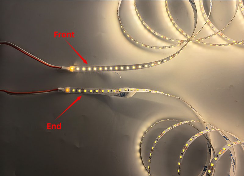
The result may be lower brightness, color variation, unstable RGB mixing or insufficient operating voltage at the end of the run. Rated voltage alone does not determine the maximum usable length: power per meter, PCB construction, feed method, cable size, connectors and operating temperature must also be considered.
Why Does the Far End of an LED Strip Become Dimmer?
The far end becomes dimmer because current must travel through the resistance of the input wiring and PCB copper before reaching the downstream LED segments.
The basic relationship is:
For a conductor, resistance increases with length and decreases as its conductive cross-section becomes larger. This is why longer runs, higher current, narrower copper paths and thinner conductors generally increase voltage drop.
An LED strip is also a distributed load. Current is consumed progressively along the strip, so the actual result depends on the complete circuit—not only a simple cable calculation.
Electrical Calculation
Voltage Drop (%) =
(Input Voltage − Far-End Voltage) ÷ Input Voltage × 100
Note: A 5% voltage drop does not automatically mean a 5% light-output reduction. Electrical voltage, current, LED behavior, brightness and color must be evaluated separately.
What Determines LED Strip Voltage Drop?
Multiple variables within the lighting circuit contribute to the final voltage measured at the far end. Engineers must evaluate the entire assembly.
| Factor | When Voltage Drop Usually Increases | What Buyers Should Verify |
|---|---|---|
| Connected length | The powered section becomes longer | Maximum length per feed |
| Power per meter | Current demand increases | Rated and stabilized measured W/m |
| System voltage | Lower voltage requires more current for the same power | 12V, 24V, 36V or 48V circuit |
| PCB construction | Copper paths are narrow or have insufficient finished thickness | PCB width, copper thickness and resistance per meter |
| Feed cable | Cable is long or undersized | Cable length, conductor size and installation route |
| Connectors and controllers | Contact or channel resistance is excessive | Rated current and measured terminal loss |
| Feed topology | Multiple runs are daisy-chained from one end | Parallel, center-feed or power-injection plan |
| Operating temperature | Copper and components operate at higher temperature | Stabilized test temperature and mounting method |
| Control mode | RGB/RGBW channels operate together at maximum load | Worst-case channel load |
Higher voltage can reduce current for the same delivered power, but it does not eliminate voltage drop. A poorly designed 48V system can still perform worse than a properly designed 24V circuit.
Does a Larger Power Supply Eliminate Voltage Drop?
Not necessarily.
A larger 24V power supply still provides approximately 24V. It may prevent the power source from becoming overloaded, but it does not remove resistance from the feed cable, connector, controller or LED strip PCB.
If the voltage is correct at the power-supply output but significantly lower at the strip input, investigate the cable, controller and connections. If the strip input is stable but the far-end voltage is low, investigate the strip length, power per meter, PCB construction and feed arrangement.
Do not increase the supply voltage above the LED strip’s approved input range simply to compensate for voltage drop. This can overdrive the LEDs closest to the power feed.
What Did Xmart’s 24V LED Strip Voltage-Drop Test Show?
Xmart compared three anonymized 24V LED strip configurations over a five-meter test length. The samples were energized from a regulated DC supply and measured at one-meter intervals after operation stabilized.
The customer name, private-label brand and complete product models are withheld under NDA. The results are presented as Configuration A, B and C.
- Dataset: Internal comparative QC data
- Test date: July 2026
- Test length: 5 meters
- Rated supply: 24V DC
- Construction tested: IP20
- Data status: model identity anonymized
| Length | Config A — 24.66W | Config B — 44.68W | Config C — 58.60W |
|---|---|---|---|
| 1 m | 23.63V / 1.54% | 23.13V / 3.63% | 23.07V / 3.88% |
| 2 m | 23.36V / 2.67% | 22.81V / 4.96% | 22.42V / 6.58% |
| 3 m | 23.16V / 3.50% | 22.47V / 6.38% | 21.95V / 8.54% |
| 4 m | 23.04V / 4.00% | 22.27V / 7.21% | 21.69V / 9.62% |
| 5 m | 23.01V / 4.12% | 22.19V / 7.54% | 21.60V / 10.00% |
Measured Voltage Drop over 5 Meters (24V DC Input)
Source: Xmart anonymized internal voltage-drop test records, July 2026
Test Conclusion
Under this internal comparison method, Configuration A remained below the project’s 5% electrical-drop criterion at five meters. Configurations B and C exceeded that criterion as connected load increased.
The result does not mean that every 24V strip with the same wattage will behave identically. PCB resistance, circuit layout, copper construction, component selection, operating temperature and feed connections can change the outcome.
The practical conclusion is that “24V, five meters” is not a complete maximum-run specification. Buyers need the voltage-drop result for the exact offered configuration.
Data Disclaimer
These measurements are anonymized internal comparative QC data, not an independent laboratory certification. They apply only to the tested samples and stated conditions and should not be extrapolated to unrelated LED strip models.
When Should Buyers Change the Power-Feed Plan?
| Observed Condition | Recommended Review |
|---|---|
| Input voltage is already below specification | Check driver loading, cable loss, controller and connectors |
| Input voltage is stable but the far end is low | Shorten the branch or add another feed point |
| Several strips are daisy-chained | Change to parallel home-run branches |
| Long cable between driver and strip | Review conductor size or move the driver closer |
| High-power strip exceeds the approved run | Use shorter sections, center feed or power injection |
| Direct-view installation shows visible variation | Apply stricter electrical and optical acceptance limits |
| Long run remains essential | Evaluate a suitable 24V, 36V or 48V long-run architecture |
| RGB/RGBW becomes discolored at full output | Test all channels at maximum expected load |
The correct response is not automatically “use a higher-voltage strip.” First identify whether the loss occurs before the strip, inside the strip or across a connector or controller.
How Should an LED Strip Voltage-Drop Test Be Performed?
- Confirm the exact LED strip model, voltage, wattage, PCB construction and intended run length.
- Fully unroll the strip before extended operation.
- Use the intended driver, controller, connectors and feed cable.
- Measure the power-supply output and the voltage directly at the strip input.
- Operate the strip at the maximum expected channel load.
- Allow voltage, current and temperature to stabilize.
- Measure voltage at 25%, 50%, 75% and 100% of the powered length.
- Record input current, total power, ambient temperature and mounting condition.
- Compare brightness and color at the same measurement positions.
- Repeat the test using the proposed mass-production configuration.
Engineering Tip
Measuring voltage with the strip switched off is not sufficient. Voltage drop must be evaluated while the system is operating under the intended load.
What Should Buyers Request From an LED Strip Manufacturer?
Do not accept “maximum run: 10 meters” without the conditions behind the claim. A useful supplier response should identify:
- Exact LED strip model and revision
- Rated and measured power per meter
- System voltage
- PCB width and finished copper specification
- Maximum powered length per feed
- Feed position and wiring topology
- Input cable length and conductor size
- Connector and controller current ratings
- Test ambient and stabilization time
- Mounting profile or surface
- IP construction
- Input, midpoint and far-end voltage
- End-to-end brightness or illuminance variation
- CCT or color variation where relevant
- Production acceptance criterion
- Required power-injection interval
This information allows a buyer to compare complete electrical designs rather than comparing voltage labels alone.
LED Strip Voltage Drop FAQs
Why is my LED strip bright at the beginning and dim at the end?
Is 5% voltage drop always acceptable for LED strips?
Will a higher-wattage power supply fix far-end dimming?
Should I increase the power-supply voltage to compensate?
Does 24V always run twice as far as 12V?
What is the best way to reduce voltage drop?
Need a Voltage-Drop Review for Your LED Strip Project?
Send Xmart the LED strip model, voltage, watts per meter, required run length, driver location, feed-cable distance, control method and target application. The engineering team can review the proposed circuit and identify the measurements needed before sample approval.
References & Standards
- OpenStax: Resistivity and Resistance
- IPC-TM-650 2.2.12: Thickness of Copper by Weight
- NIST Copper Wire Tables
- Xmart anonymized internal voltage-drop test records, July 2026