
How to Plan Power Injection for Long LED Strip Runs
Power injection adds the correct supply voltage at additional points along an LED strip installation. Its purpose is to shorten the current path and control voltage drop—not to increase the strip voltage.
The correct feed layout depends on the exact LED strip model, measured watts per meter, continuous electrical length, PCB construction, cable distance, connector rating and access to feed locations.
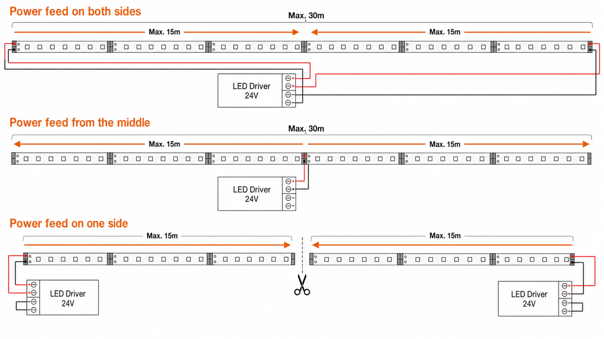
Where Should Power Be Injected on a Long LED Strip?
Power should be added before the measured or predicted voltage drop exceeds the project’s agreed limit. The injection point is therefore model- and project-specific.
For some installations, feeding both ends of one continuous strip may be sufficient. Other projects are better divided into center-fed sections or shorter parallel branches. A larger LED driver alone does not reduce resistance in the strip PCB.
Power injection does not correct an undersized driver. The driver must still support the complete connected load, while every cable, connector, controller channel and LED strip section must remain within its own electrical limit.
Four Common LED Strip Power-Feed Layouts
Understanding the physical and electrical flow of each architecture is critical for commercial LED strip installation.
1. Single-End Feed
The complete strip is powered from one end. It is the simplest layout, but the input cable, first connection and first PCB section carry the current for the entire run.
- The tested single-feed length covers the required run;
- The load is relatively low;
- The far-end voltage remains within the approved project limit.
2. Two-End Feed
Driver
The same continuous LED strip receives the correct voltage and polarity from both ends. Current travels inward from two directions, reducing the longest current path through the PCB.
- Both ends of the installation are accessible;
- A continuous unbroken light line is required;
- Testing confirms that the center of the run remains within the approved limit.
3. Center Feed
Power enters near the center and travels outward in two directions. Electrically, the installation becomes two shorter branches even though it may appear as one continuous line.
- The driver or distribution point can be located near the center;
- Both directions use compatible strip sections;
- Balanced cable routing is possible.
4. Parallel Branches
Dist.
Each branch receives a separate V+ and V− feed from a distribution point rather than passing the full project current through the first LED strip reel.
- The project contains several coves, shelves or architectural sections;
- Total installed length is large;
- Each branch can remain within the tested maximum electrical length;
Which Power-Feed Layout Fits the Project?
| Layout | Main Advantage | Main Constraint | Suitable Project Condition |
|---|---|---|---|
| Single-end feed | Fewest connections | Longest PCB current path | Short, tested runs |
| Two-end feed | Reduces maximum path to the center | Both ends must be accessible | One continuous physical line |
| Center feed | Creates two shorter electrical directions | Central access is required | Long coves and corridors |
| Parallel branches | Prevents one strip section carrying the full project current | More home-run cables | Multiple fixtures, shelves or zones |
| Distributed drivers | Can reduce long low-voltage cable runs | More driver locations and service points | Large projects with accessible driver positions |
The best layout is not always the one with the fewest drivers or cables. Buyers should compare electrical performance, installation labor, access, maintenance and connection count.
What Must Be Calculated Before Adding a Power Feed?
Engineering a reliable long-run installation requires calculating the limits of every component in the circuit.
Total Connected Load
This determines the approximate connected load, but it does not determine the permitted single-feed length.
Branch Current
Calculate each branch separately. RGB, RGBW, tunable-white and addressable strips may have different maximum-load conditions depending on the active channels.
Feed-Cable Voltage Drop
Both outgoing and return conductors contribute to the cable path. Cable length, conductor area, material, temperature and connection resistance must be included.
4. Maximum Strip Length per Feed
Use the exact model’s datasheet or measured voltage-drop result. Do not derive the permitted single-feed length from driver wattage alone.
5. Component Limits
- Driver output capacity and derating requirements
- Dimmer or controller channel current
- Connector current rating
- Solder-pad and lead-wire capacity
- Distribution terminal rating
- Applicable Class 2 or local electrical limits
- Thermal conditions around the driver and strip
Do not apply one universal “80% rule” or “90% rule” to every driver. Follow the selected driver manufacturer’s loading, ambient-temperature and derating requirements.
What Did Xmart’s 24V Voltage-Drop Test Show?
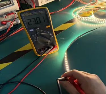
Xmart compared three anonymous 24V, 5-meter LED strip configurations using 24.00V measured at the strip input.
At 5 meters, the recorded voltage drop was:
- Sample A: 4.12% at 24.66W total measured power
- Sample B: 7.54% at 44.68W total measured power
- Sample C: 10.00% at 58.60W total measured power
Under the 5% internal comparison line used for that test, Sample A remained below 5% through 5 meters, Sample B through 2 meters and Sample C through 1 meter.
The three samples used the same nominal voltage and test length but produced different results. This is why Xmart does not assign one universal power-injection distance to every 24V LED strip.
A Practical Power-Injection Decision Process
Follow this systematic approach to design a reliable commercial LED strip installation.
Define the Physical Installation
Record total length, separate sections, corners, profiles and available driver locations.
Confirm the Exact Strip Configuration
Confirm voltage, measured watts per meter, PCB width, copper construction, channel type and model-specific maximum run.
Set the Acceptance Requirement
Agree on the permitted electrical voltage drop and any required brightness or color-uniformity tolerance.
Select a Feed Architecture
Compare single-end, two-end, center, parallel-branch and distributed-driver options.
Check Every Current Path
Check the driver, supply cable, connector, controller, solder joint and LED strip branch—not only total driver wattage.
Verify the Final Assembly
Test the approved strip, cable, connectors, driver, controller and feed positions after current and temperature have stabilized.
Example: A 24V Strip That Exceeds the Project Limit at 5m
An anonymous 24V sample measured 44.68W over 5 meters. It recorded 4.96% voltage drop at 2 meters, 6.38% at 3 meters and 7.54% at 5 meters.
Decision
Do not approve the complete 5-meter section as a single-end feed under the 5% internal comparison criterion.
Next design candidates
- Feed the continuous run from both ends;
- Introduce a center feed;
- Divide the installation into shorter parallel branches;
- Evaluate a compatible higher-voltage or purpose-built long-run strip.
Verification
The selected layout must be retested with the final cable length, wire size, connectors, profile and driver. The original single-end measurements cannot be mathematically converted into guaranteed two-end or center-feed performance without verification.
Review the test data →Common Power-Injection Planning Mistakes
Choosing a Larger Driver Only
A larger driver increases available power but does not reduce resistance in the strip PCB.
Daisy-Chaining Multiple Reels
Passing the complete project current through the first reel can exceed the tested run length, connection rating or controller output.
Ignoring Feed-Cable Loss
A correctly selected strip can still receive insufficient voltage if the cable between the driver and feed point is too long or too small.
Treating Every 24V Strip the Same
Two 24V strips can have different wattage, PCB construction, cut length, circuit layout and maximum run.
Combining Independent Driver Outputs
Do not connect two independent DC driver outputs to the same electrical section unless that operating mode is expressly approved by the driver manufacturer.
Testing Only on the Reel
Do not operate high-power LED strip tightly wound on a reel. Test the installed or safely laid-out sample under representative thermal conditions.
Does Power Injection Work the Same for Every LED Strip?
Single-Color Strip
Normally uses V+ and V−, but the complete current path and polarity must still be checked.
Tunable White and RGB/RGBW Strip
Multiple output channels are involved. Controller-channel current and conductor allocation must be verified under the maximum intended channel combination.
Addressable LED Strip
Power and data planning are separate. Additional power feeds must preserve the required ground reference and follow the selected IC and controller wiring requirements.
Long-Run Constant-Current Strip
On-board current-control components may extend the usable run, but the exact model still requires a defined voltage, load, maximum length and measured endpoint result.
What Should Buyers Provide for a Power-Feed Review?
- Exact LED strip model or requested construction
- Operating voltage
- Target or measured watts per meter
- Total installed length
- Longest continuous physical section
- Driver and controller information
- Distance from driver to each feed point
- Cable size or available cable space
- Available start, end and center access
- Profile, ambient temperature and installation environment
- Required certification or Class 2 constraints
- Acceptable voltage, brightness or color variation
Xmart can use this information to propose a sample test plan. Final feed positions should be approved using the actual production-intent strip and installation components.
LED Strip Power Injection Questions
What is LED strip power injection?
How often should power be injected into an LED strip?
Is feeding an LED strip from both ends always safe?
Can a larger LED driver eliminate the need for power injection?
Is center feeding better than feeding both ends?
Can several LED strip branches share one driver?
Should power injection be decided before ordering an OEM LED strip?
Important Safety Note
Electrical installation must follow the selected product instructions and applicable local codes. Low-voltage LED strip must not be connected directly to AC line voltage. Driver selection, branch protection and field wiring should be completed or reviewed by a qualified electrical professional.
Plan the Power Architecture Before Approving the Strip
Send Xmart the operating voltage, watts per meter, continuous length, driver location, cable distance and available feed points. We can help define which electrical arrangement should be sampled and verified before mass production.
Email Us
info@xmartlighting.comCall Us
+86 15874715712