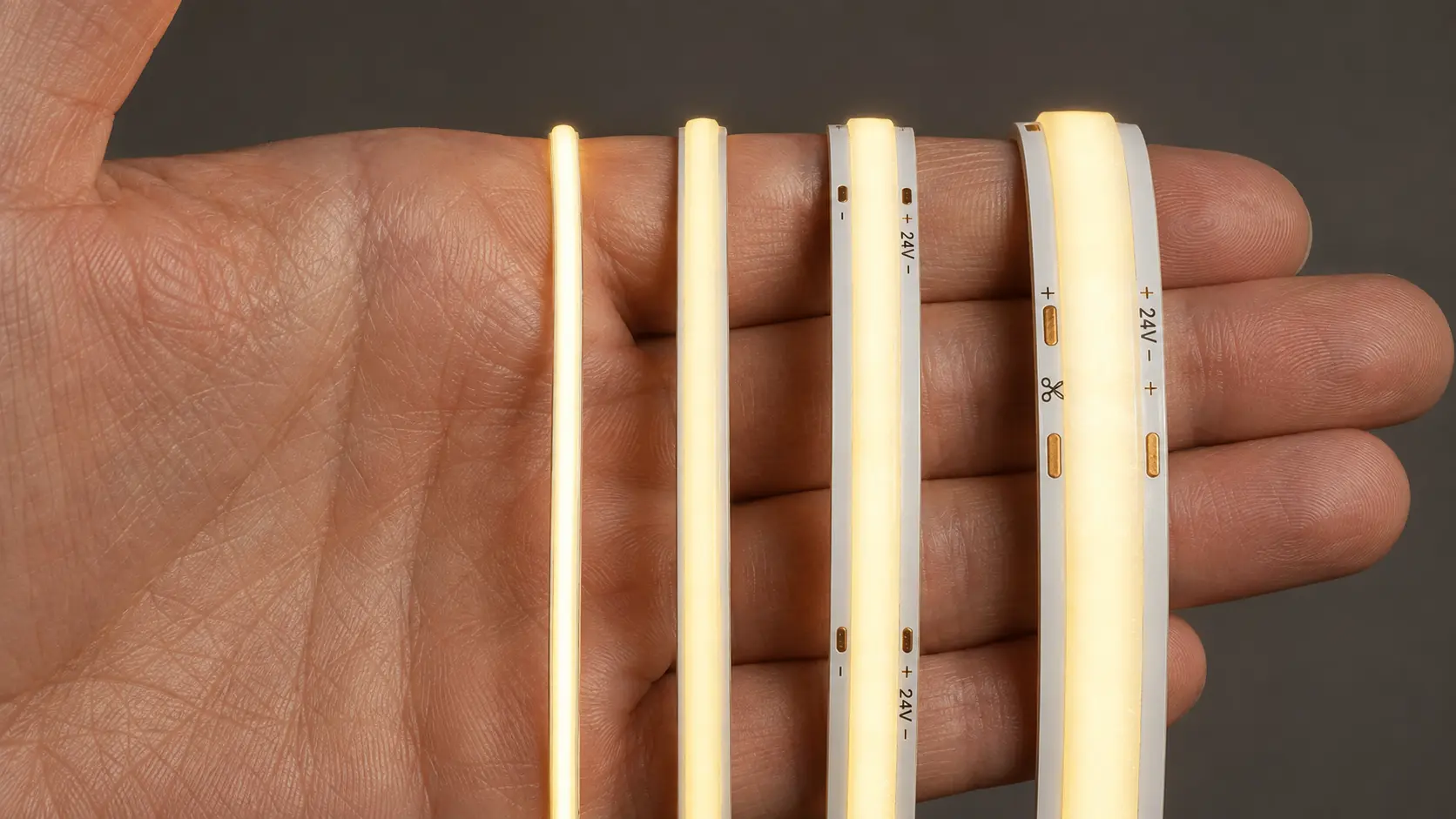
Yes, LED strip PCB width matters—but not because a wider strip is automatically brighter, cooler or better.
PCB width affects how much space is available for:
- Positive and negative power rails
- Multiple color channels
- Copper pads and connectors
- LED packages and resistors
- Heat spreading
- Adhesive contact
- Waterproof encapsulation
- Mechanical handling
However, PCB width alone does not determine voltage drop, current capacity or lifespan.
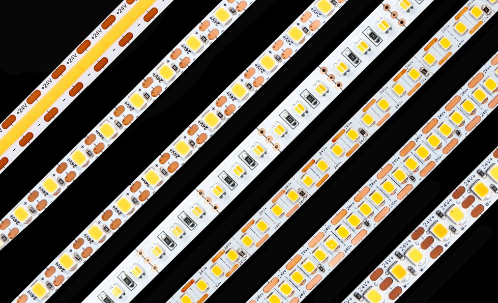
A well-designed 5mm strip using thick copper, efficient LEDs and a 24V circuit can outperform a poorly designed 10mm strip. A 12mm strip may provide more room for RGBW channels, yet still suffer serious voltage drop if its shared positive rail is too narrow.
The correct question is not:
Is a 12mm PCB better than a 5mm PCB?
It is:
Is the PCB width appropriate for the electrical load, channel count, thermal conditions and installation space?
Quick Answer: Which LED Strip Width Should You Choose?
- Choose 5mm when installation space is extremely limited and the strip has been engineered specifically for narrow profiles.
- Choose 8mm for compact single-color or COB lighting where a good balance of size, electrical performance and compatibility is required.
- Choose 10mm when the strip needs more PCB area for higher power, larger LEDs, tunable white, RGB or stronger connection pads.
- Choose 12mm for RGBW, RGBCCT, multi-row or higher-current designs that genuinely use the additional width for copper and circuit routing.
If more than one width can physically fit, do not select by width alone. Compare copper thickness, effective power-rail width, W/m, voltage drop, operating temperature and connector compatibility.
5mm vs 8mm vs 10mm vs 12mm: Comparison Table
| PCB width | Main advantage | Main limitation | Common product types | Typical applications |
|---|---|---|---|---|
| 5mm | Fits extremely narrow spaces | Limited copper, pad and component area | Ultra-narrow SMD, slim COB, specialized tunable white or RGB | Furniture, mirrors, shelves, display cases and product integration |
| 8mm | Compact but more practical electrically | Less routing room than 10mm or 12mm | Single-color SMD, COB and some tunable-white strips | Cabinets, coves, profiles and general architectural lighting |
| 10mm | Good balance of electrical and mechanical space | Requires a larger profile than 5mm or 8mm | Single color, COB, RGB, tunable white and higher-power strips | Commercial interiors, retail, hospitality and architectural projects |
| 12mm | More room for channels, rails and larger pads | Wider profiles, connectors and grooves are required | RGBW, RGBCCT, multi-row and higher-current products | Color-changing systems, entertainment, hospitality and custom luminaires |
These are common use patterns, not universal rules. Manufacturers can produce specialized circuit designs in almost any of these widths.
What Does PCB Width Actually Measure?
LED strip PCB width normally refers to the width of the bare flexible printed circuit board.
For example:
- A 5mm strip has a bare PCB approximately 5mm wide.
- An 8mm strip has a bare PCB approximately 8mm wide.
- A 10mm strip has a bare PCB approximately 10mm wide.
- A 12mm strip has a bare PCB approximately 12mm wide.
But the finished product can be wider than the bare PCB.
The final width may increase because of:
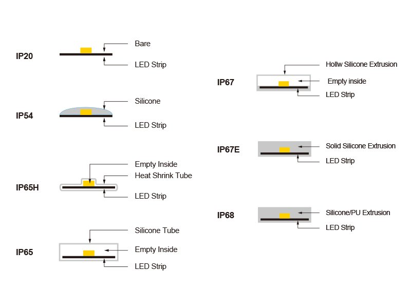
- Silicone coating
- Heat-shrink tubing
- Silicone extrusion
- Hollow waterproof sleeves
- Polyurethane encapsulation
- Side walls around COB phosphor
- Waterproof connectors
- End caps and cable exits
This distinction is critical when the strip must fit inside a narrow aluminum profile.
Do not order a waterproof “10mm LED strip” based only on the PCB width. Request the finished outer dimensions of the waterproof product, including its manufacturing tolerance.
The Most Important Distinction: PCB Width Is Not Copper Rail Width
The entire PCB width is not available for carrying power.
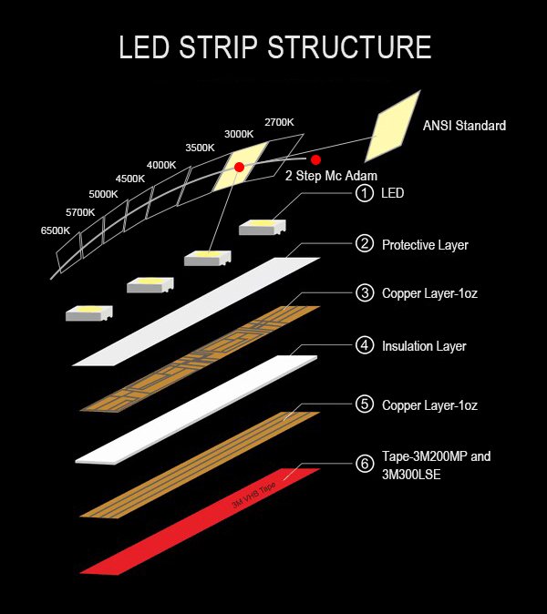
The PCB also needs space for:
- LEDs
- Resistors
- Constant-current ICs
- Addressable control ICs
- Data traces
- Color-channel traces
- Solder pads
- Cut marks
- Clearances between conductors
- Mechanical margins at the PCB edges
A 10mm PCB may contain two wide power rails—or several narrow channels competing for the same space.
This is particularly important for:
- RGB
- RGBW
- Tunable white
- RGBCCT
- Addressable LED strips
Therefore, buyers should distinguish between:
- Total PCB width
- Effective power-rail width
- Copper thickness
- Narrowest point in the current path
The effective electrical cross-section is approximately:
Copper cross-section = effective rail width × copper thickness
That cross-section, rather than the printed PCB width, directly affects conductor resistance.
Why a 5mm PCB Can Outperform a 10mm PCB
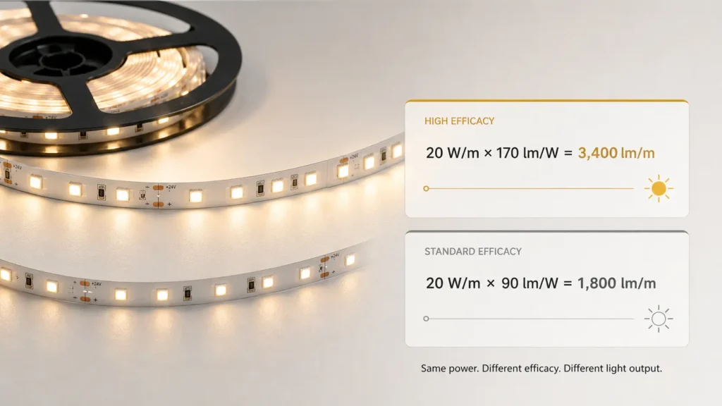
Consider two hypothetical LED strip designs.
Strip A
- PCB width: 5mm
- Effective power-rail width: 1.2mm
- Copper thickness: 2 oz, approximately 70µm
Copper cross-section:
1.2mm × 0.070mm = 0.084mm²
Strip B
- PCB width: 10mm
- Effective power-rail width: 2mm
- Copper thickness: 1 oz, approximately 35µm
Copper cross-section:
2mm × 0.035mm = 0.070mm²
Despite having half the total PCB width, Strip A has a larger power-rail cross-section in this simplified comparison.
If copper type, length and temperature are equal, its power rail can have lower resistance.
This example does not prove that 5mm is better than 10mm. It proves that the external width cannot reveal the electrical performance of the internal layout.
IPC’s guidance on printed-board conductors evaluates conductor width, thickness, current and acceptable temperature rise together. It does not treat total PCB width as a current rating. See the official IPC-2152 overview.
How PCB Width Affects Voltage Drop
Voltage drop follows:
Vdrop = Current × Resistance
PCB conductor resistance can be approximated by:
R = ρL ÷ A
Where:
- ρ is copper resistivity
- L is conductor length
- A is conductor cross-sectional area
A wider PCB can reduce voltage drop only if the designer uses the additional space to increase the copper cross-section of the power rails.
A wider strip will not significantly improve voltage drop when the extra space is consumed by:
- Additional color channels
- Larger component clearances
- Decorative printing
- Multiple rows of LEDs
- Narrow neck-downs around cutting points
- Small input pads
- Poorly arranged circuit sections
The most useful supplier data is not simply “10mm PCB.” It is:
- Finished copper thickness
- Effective positive rail width
- Effective negative rail width
- Maximum tested run length
- Start and far-end voltage
- Input and far-end brightness
- Test temperature and mounting method
Wider PCBs Can Reduce Voltage Drop—But Higher Voltage May Matter More
Suppose two LED strips have the same power per meter.
A 12V strip draws twice as much current as a 24V strip at the same power:
Current = Power ÷ Voltage
Because PCB heating follows:
Copper loss = I²R
Moving from 12V to 24V reduces current by half and conductor heating to approximately one-quarter, assuming the same power and resistance.
This means a well-designed 24V 5mm strip can have better voltage-drop performance than a wider 12V strip.
For long runs, compare these options before automatically choosing a wider PCB:
- Increase PCB width
- Increase copper thickness
- Move from 12V to 24V
- Move from 24V to 36V or 48V
- Feed from both ends
- Center-feed the strip
- Divide the installation into parallel branches
- Use a constant-current regulated strip
PCB width is only one of several ways to manage current distribution.
Does a Wider PCB Dissipate Heat Better?
Usually, yes—but the improvement is conditional.
At the same watts per meter, a wider PCB spreads the thermal load across a larger surface area.
For example, ignoring component distribution:
- One meter of 5mm PCB has approximately half the surface area of one meter of 10mm PCB.
- At the same W/m, the narrower strip has approximately twice the average power per unit of PCB area.
A wider PCB can potentially provide:
- More copper area for lateral heat spreading
- More contact area with mounting tape
- More contact area with an aluminum profile
- Less concentrated heating around LEDs and resistors
- More space between heat-generating components
But a wider PCB does not automatically run cooler.
Operating temperature still depends on:
- LED efficacy
- Actual input power
- Copper thickness and layout
- PCB dielectric construction
- Solder-pad design
- Adhesive thickness
- Air gaps
- Aluminum-profile size
- Ambient temperature
- Waterproof encapsulation
- Enclosure ventilation
A 12mm strip installed on wood can run hotter than an 8mm strip installed correctly in a substantial aluminum profile.
The thermal path remains:
LED junction → LED package → solder pad → PCB → adhesive → profile → surrounding air
If the strip does not make good contact with the profile, the additional PCB width provides less benefit than expected.
The Aluminum Profile Is Part of the Width Decision
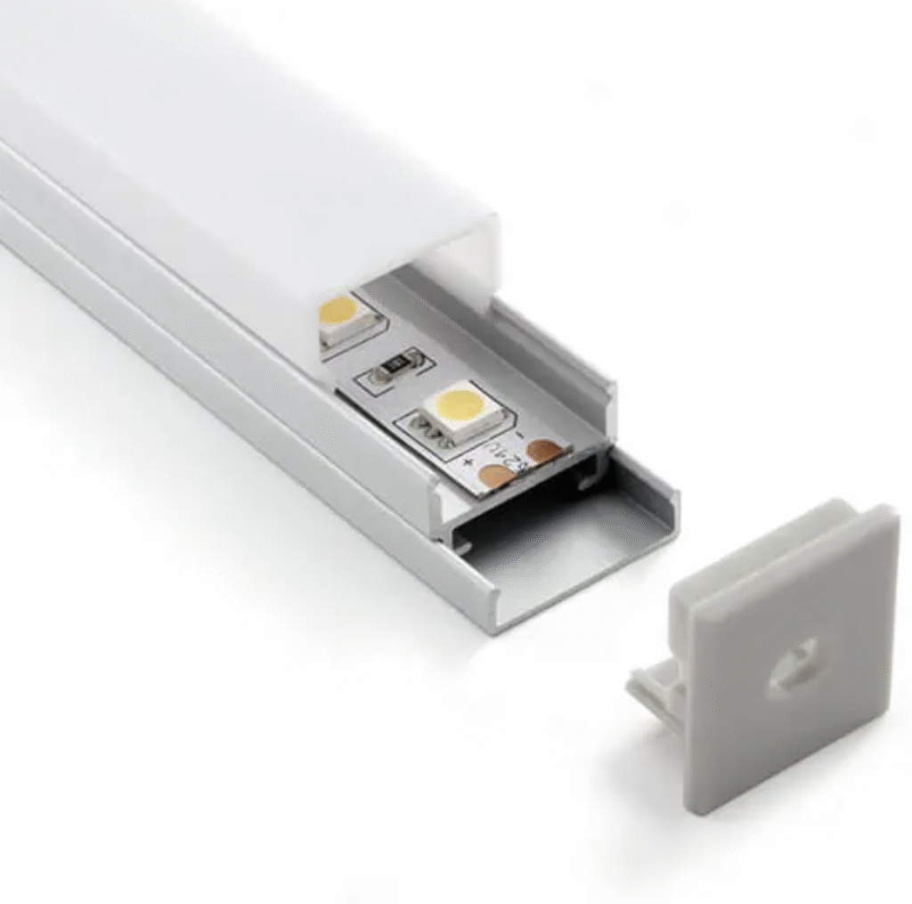
The strip must fit inside the usable inner width of the profile—not the profile’s advertised external width.
As a practical installation allowance, the inner width should normally be approximately 0.5mm to 1mm wider than the finished strip. This allows room for installation tolerances and minor thermal or dimensional movement. Xmart provides this matching guidance in its LED aluminum profile selection information.
A simplified starting point is:
| Finished strip width | Practical minimum profile inner width* |
| 5mm | Approximately 5.5–6mm |
| 8mm | Approximately 8.5–9mm |
| 10mm | Approximately 10.5–11mm |
| 12mm | Approximately 12.5–13mm |
*Confirm actual product tolerances, waterproof dimensions, connector size and installation method before ordering.
Also check:
- Whether the solder joint fits under the diffuser
- Whether wires can exit without lifting the strip
- Whether solderless connectors fit inside the channel
- Whether profile clips or screws reduce internal clearance
- Whether the strip can be replaced after installation
- Whether the diffuser creates sufficient distance for uniform light
A strip that technically fits but must be forced into the channel may lift from the profile, damage its edges or create poor thermal contact.
5mm LED Strip: Compact but Electrically Constrained
A 5mm LED strip is designed for spaces where conventional 8mm or 10mm products cannot fit.
Typical applications include:
- Mirror-edge lighting
- Shelf grooves
- Display cabinets
- Furniture lighting
- Product housings
- Narrow signage
- Miniature aluminum profiles
- Equipment-integrated lighting
Advantages of a 5mm PCB
- Fits narrow grooves
- Supports discreet installations
- Allows smaller aluminum profiles
- Works well in furniture and product integration
- Can create a very narrow visible line of light
- Reduces the installation footprint
Limitations of a 5mm PCB
- Less space for wide power rails
- Smaller solder pads
- More demanding manual soldering
- Limited solderless connector availability
- Higher thermal concentration at the same W/m
- Less room for multiple color channels
- Greater sensitivity to PCB layout quality
- More reliance on an aluminum heat sink
Xmart’s ultra-narrow LED strip range includes specialized 2mm to 5mm constructions for furniture, displays and compact lighting integration. These narrow products require careful matching of voltage, wattage, PCB layout and thermal mounting.
A 5mm strip should not be selected merely because it is smaller. It should be selected because the installation genuinely requires a narrow solution.
8mm LED Strip: The Compact General-Purpose Option
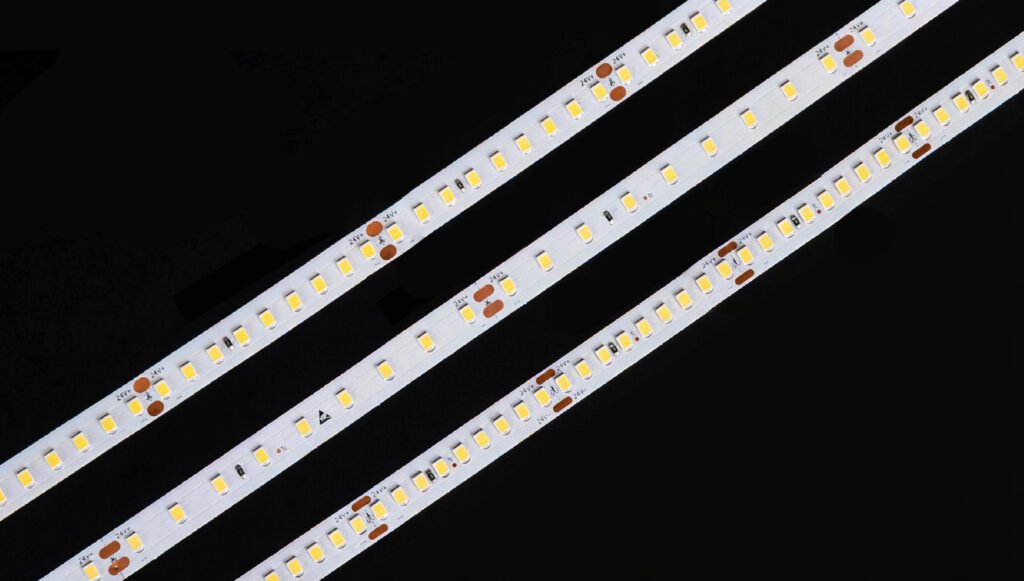
An 8mm PCB is common for single-color SMD and COB LED strips.
It often provides enough room for:
- Two practical power rails
- Standard single-color circuit sections
- Moderate solder pads
- Common LED packages
- Standard cut points
- Compact aluminum profiles
Advantages of an 8mm PCB
- Fits many compact profiles
- Better electrical and thermal area than 5mm
- Widely available for white and COB strips
- Easier to solder than many 5mm products
- Good balance of size and performance
Limitations of an 8mm PCB
- May still be restrictive for RGBW or RGBCCT
- Connector compatibility must be checked carefully
- High W/m can still produce concentrated heat
- Narrow rails may remain a problem on poorly designed layouts
- Not every 8mm product uses the same pad spacing
For general white architectural lighting, an 8mm strip is often sufficient when its voltage, copper construction and profile are appropriate.
10mm LED Strip: The Flexible Project Standard
Ten-millimeter PCBs provide more room for circuit design without requiring an unusually wide installation channel.
They are commonly used for:
- Higher-output single-color strips
- Tunable-white strips
- RGB strips
- COB LED strips
- Larger LED packages
- Commercial architectural lighting
- Retail and hospitality installations
Advantages of a 10mm PCB
- More room for power rails
- Larger and easier solder pads
- Better support for multiple channels
- More contact area with the aluminum profile
- Broad connector and profile availability
- Greater freedom for component spacing
- Potentially better thermal distribution
Limitations of a 10mm PCB
- Does not fit very narrow furniture grooves
- Requires a larger channel than 5mm or 8mm
- Width does not guarantee thick copper or low voltage drop
- Some waterproof versions become substantially wider
- Multi-channel circuits may consume the extra routing space
A 10mm PCB is often a safe starting point for professional projects, but its measured performance remains more important than the dimension.
12mm LED Strip: More Circuit Space, Not Automatically More Light
A 12mm PCB is commonly associated with more complex or higher-current products, including:
- RGBW
- RGBCCT
- High-output COB
- Multi-row LED strips
- Larger LED packages
- Specialized architectural products
Advantages of a 12mm PCB
- More space for shared power rails
- More room for four, five or six conductors
- Larger solder and connector pads
- Better mechanical handling during installation
- More heat-spreading and contact area
- Potential support for multiple LED rows
Limitations of a 12mm PCB
- Requires wider profiles
- Wider solderless connectors are needed
- Larger grooves may affect furniture or architectural details
- Waterproof construction increases the finished width further
- Higher material and accessory costs are possible
- It is more difficult to route through compact curves or transitions
A 12mm strip is not automatically brighter than an 8mm strip. Brightness is determined mainly by actual LED output, power, efficacy, thermal conditions and optical losses.
The additional width creates design opportunity. It does not guarantee that the manufacturer used that opportunity effectively.
Multi-Channel Strips Need More Than Physical Width
RGB, RGBW, tunable-white and RGBCCT strips require multiple electrical paths.
For example, an RGBW strip may need:
- One shared positive rail
- Red return
- Green return
- Blue return
- White return
An RGBCCT strip may require even more conductors.
The shared positive rail can carry the combined current of several active channels. If the manufacturer prioritizes channel count while leaving the common rail too narrow, a 12mm strip can still experience:
- Excessive voltage drop
- Input-end heating
- Color shift
- Reduced far-end brightness
- Uneven mixed white
- Overloaded connectors
When evaluating multi-channel strips, request test results for realistic operating states—not only one color channel at a time.
Useful tests include:
- RGB mixed white
- Dedicated white at full output
- RGB and white operating simultaneously
- Warm and cool white channels operating together
- Maximum controller-permitted combined output
The worst-case shared-rail current may be more important than the PCB’s external width.
Does a Wider Strip Produce More Uniform, Dotless Light?
Not necessarily.
Visible LED dots are influenced by:
- LED spacing
- LED package size
- COB phosphor coverage
- Distance between LEDs and diffuser
- Profile depth
- Diffuser transmission
- Diffuser material
- Viewing angle
- Surface reflectivity
A 12mm strip with widely spaced LEDs can show more visible dots than a 5mm high-density strip.
A narrow COB strip can also create a continuous line of light because the phosphor layer blends the individual chip output. Xmart offers COB LED strips in multiple PCB widths to match different profiles and circuit requirements.
However, “dotless” does not mean the strip has unlimited brightness or perfect heat dissipation. Narrow COB strips still need adequate copper, sensible W/m and proper mounting.
Does PCB Width Affect Beam Angle?
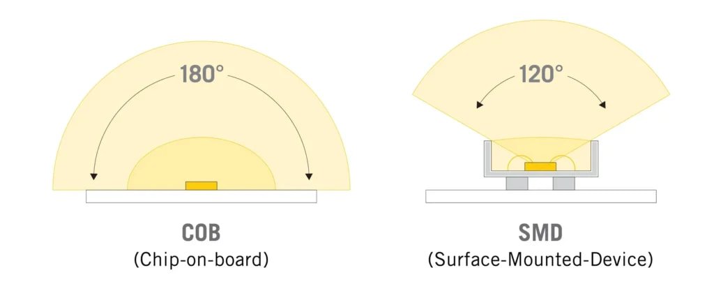
PCB width can influence the apparent emitting width, but it does not independently determine beam angle.
The result depends more strongly on:
- LED lens construction
- COB phosphor geometry
- Number of LED rows
- Reflective surfaces
- Aluminum-profile shape
- Diffuser curvature
- Recess depth
A wider multi-row strip may create a broader luminous surface. A narrow strip may create a finer line. But the final photometric effect should be verified using the complete strip-and-profile assembly.
Does a Narrower PCB Bend More Easily?
Usually, a narrow PCB is easier to route through confined spaces and can feel more flexible. However, this does not make it a side-bending LED strip.
A standard LED strip is normally designed to bend along its intended axis. It should not be:
- Folded sharply
- Twisted repeatedly
- Bent across components
- Creased at solder joints
- Forced around a lateral curve
For letters, curved signage and irregular lateral paths, use an appropriate zigzag, S-shape or side-bending product.
The correct bend behavior also depends on:
- Copper thickness
- Copper type
- PCB layer count
- Polyimide thickness
- Component spacing
- Solder-joint position
- Waterproof encapsulation
- Minimum bend radius
A 5mm PCB with 3 oz copper may be less flexible than an 8mm PCB with 1 oz copper.
Once again, width is only one variable.
Connector and Solder-Pad Compatibility
PCB width affects which connectors can be used, but equal-width connectors are not automatically interchangeable.
A connector must match:
- PCB width
- Number of conductors
- Pad pitch
- Pad position
- Copper-pad length
- Strip thickness
- Waterproof or non-waterproof construction
- Maximum current
- Installation environment
A 10mm single-color connector cannot be assumed to fit a 10mm RGB or COB strip.
Narrow strips create additional challenges:
- Smaller contact surfaces
- Less tolerance for misalignment
- Smaller solder pads
- More difficult strain relief
- Higher contact resistance if clamping is poor
For high-current and long-run installations, a correctly soldered cable may provide better reliability than a compact solderless connector.
Waterproof LED Strip Width Requires Separate Verification
Waterproofing can change both the physical and thermal behavior of the strip.
A bare 8mm PCB may become too wide for an 8.5mm channel after it receives:
- Silicone coating
- A silicone sleeve
- Solid extrusion
- PU encapsulation
- End sealing
- A molded connector
Before production, request:
- Bare PCB width
- Finished waterproof width
- Finished waterproof height
- Maximum dimensional tolerance
- Minimum profile inner width
- Connector outer dimensions
- End-cap dimensions
- Cable-exit direction
The waterproof layer may also reduce heat transfer from the PCB to the aluminum profile. In that case, simply choosing a wider PCB does not guarantee lower operating temperature.
Test the actual waterproof construction in the intended profile.
Width and Manufacturing Cost
A wider PCB generally uses more:
- Flexible laminate
- Copper
- Coverlay or solder mask
- Adhesive tape
- Silicone or encapsulation material
It may also require:
- Wider connectors
- Wider aluminum profiles
- Larger packaging
- More installation space
However, a 5mm strip is not always cheaper than a 10mm strip.
Ultra-narrow designs may cost more because they require:
- Smaller LED packages
- More precise component placement
- Tighter PCB tolerances
- Specialized soldering
- Custom connectors
- Higher manufacturing control
- Lower-volume components
- More difficult handling
Therefore, PCB width and price are not directly proportional.
The correct cost calculation is:
Total installed cost = strip + profiles + connectors + wiring + installation labor + maintenance risk
A slightly wider standard product may be less expensive overall than a highly customized narrow strip.
Five Questions That Determine the Right PCB Width
1. What Is the Maximum Available Installation Width?
Measure the narrowest usable space, including turns, clips, connectors and cable exits.
2. What Is the Electrical Load?
Confirm:
- Voltage
- W/m
- Total length
- Current per feed
- Number of channels
- Dimming conditions
3. What Thermal Path Is Available?
Determine whether the strip will be mounted on:
- Aluminum profile
- Steel
- Stone
- Glass
- Wood
- Plastic
- Painted drywall
- An enclosed cavity
4. Which Accessories Must Fit?
Check the complete system:
- Profile
- Diffuser
- End caps
- Solderless connectors
- Cables
- Mounting clips
- Waterproof seals
5. How Will the Strip Be Installed and Serviced?
Consider:
- Minimum cut length
- Soldering access
- Replacement access
- Power-injection points
- Bend direction
- Waterproof joint construction
- Maintenance requirements
The smallest strip that fits is not necessarily the best strip. Leave enough space for installation, heat transfer and reliable connections.
How to Compare Samples from Different Suppliers
When comparing 5mm, 8mm, 10mm or 12mm products, use the same test conditions.
Record the Construction
Document:
- Bare PCB width
- Finished width
- Copper thickness
- PCB layer count
- Effective power-rail width
- LED package
- LED density
- Voltage
- W/m
- Cut length
- Waterproof construction
Test the Full Intended Run
Do not compare one-meter samples if the project will use five-meter or ten-meter runs.
Measure:
- Voltage at the power supply
- Voltage at the strip input
- Voltage at the midpoint
- Voltage at the far end
- Total input current
- Start and far-end brightness
- Start and far-end color
- PCB temperature
- Profile temperature
Use the Intended Profile
A strip tested in open air cannot represent performance inside:
- A small recessed profile
- A closed cabinet
- A silicone tube
- An insulated ceiling
- A waterproof enclosure
Allow Thermal Stabilization
Record final measurements only after the strip approaches a stable operating temperature.
A wider strip may look better during the first few minutes but show a different result after the complete assembly becomes warm.
A Better PCB Width Specification
Instead of writing:
10mm LED strip required
Use a performance-based specification:
24V LED strip with maximum finished PCB width of 10mm, 2 oz nominal copper, minimum effective power-rail width as approved, 9.6W/m nominal power, five-meter single-end feed, maximum 3% measured voltage drop and maximum 10% start-to-end luminous variation after thermal stabilization in the specified aluminum profile.
For waterproof products, add:
- Maximum finished encapsulated width
- Maximum finished height
- Approved silicone or PU material
- Minimum profile clearance
- Joint and connector dimensions
For multi-channel strips, add:
- Maximum combined current
- Common-rail construction
- Controller operating mode
- Test state for simultaneous channels
This prevents a supplier from meeting the width requirement while missing the actual performance requirement.
Recommended Starting Points
| Project requirement | Suggested starting width |
| Extremely narrow furniture or product cavity | 5mm |
| Compact white or COB profile lighting | 8mm |
| General professional architectural strip | 8mm or 10mm |
| Higher-output white strip | 10mm |
| Tunable white | 8mm or 10mm, depending on layout |
| RGB | 10mm is common; specialized 5mm versions are possible |
| RGBW | 10mm or 12mm |
| RGBCCT | 12mm or wider is often more practical |
| Multi-row LED strip | 12mm or wider |
| Waterproof strip inside a profile | Select by finished outer width, not bare PCB |
| Long-run installation | Select by voltage drop and feed design, not width alone |
These are engineering starting points, not fixed rules.
Frequently Asked Questions
Is a wider LED strip brighter?
Not automatically. Brightness depends on LED output, LED quantity, current, W/m, efficacy, temperature and optical losses. A 5mm strip can be brighter than a 12mm strip.
Does a 12mm PCB have less voltage drop than a 5mm PCB?
Only if the wider design has a larger effective copper cross-section or a better circuit layout. Copper thickness, rail width, voltage and feed method must also be compared.
Is a 5mm LED strip safe?
Yes, if its voltage, wattage, copper layout, run length and thermal mounting are appropriate. Narrow high-power strips require particularly careful heat management.
Does an ultra-narrow LED strip require an aluminum profile?
For moderate or high-power operation, mounting on an aluminum profile or suitable heat-dissipating surface is strongly recommended. The exact requirement should follow the manufacturer’s thermal test conditions.
Can I install a 10mm strip in a 10mm-wide profile?
Usually not if 10mm is the profile’s exact inner width. Allow installation clearance and confirm the strip’s finished tolerance. Waterproof products require additional space.
Are all 8mm connectors compatible with all 8mm strips?
No. The number of channels, pad pitch, strip thickness, COB construction and waterproofing must also match.
Is an 8mm COB strip more dotless than a 10mm SMD strip?
It may appear more continuous because COB uses a phosphor-covered emitting surface, but the final result depends on diffuser distance, profile depth, density and viewing conditions.
Does a wider PCB improve LED lifespan?
It can support better heat spreading and lower conductor resistance, but lifespan depends on the complete thermal and electrical design. A wider PCB cannot compensate for excessive power or poor mounting.
Can I replace a 12mm strip with a 10mm strip?
Physically, it may fit. Electrically and optically, it may not be equivalent. Compare voltage, power, lumen output, channel configuration, connector type, cut length and thermal performance.
Final Recommendation
LED strip PCB width is an engineering constraint—not a quality grade.
A wider PCB can provide more room for copper rails, components, channels, solder pads and heat spreading. But those advantages exist only when the layout uses the extra width effectively.
Remember these principles:
- PCB width is not the same as power-rail width.
- Copper thickness and effective rail width must be evaluated together.
- A narrow 2 oz PCB can outperform a wider 1 oz PCB.
- Higher system voltage may reduce voltage drop more than additional width.
- A wider PCB does not automatically produce more lumens.
- Dotless appearance depends on density and optical design, not PCB width alone.
- Waterproof dimensions must be checked after encapsulation.
- Profile inner width should include installation clearance.
- Multi-channel strips require special attention to the shared power rail.
- Full-length electrical and thermal testing is more valuable than a width claim.

As a custom LED strip manufacturer, Xmart Lighting supports PCB widths from ultra-narrow formats to wider multi-channel constructions. The appropriate solution is selected by combining installation dimensions, voltage, W/m, copper thickness, control channels, run length, waterproofing and aluminum-profile requirements.
For project or OEM evaluation, provide the available groove width, required output, total run length, feed locations, IP construction and control type. That information allows the PCB width to be engineered around the application—instead of forcing the application to accept an unsuitable strip.