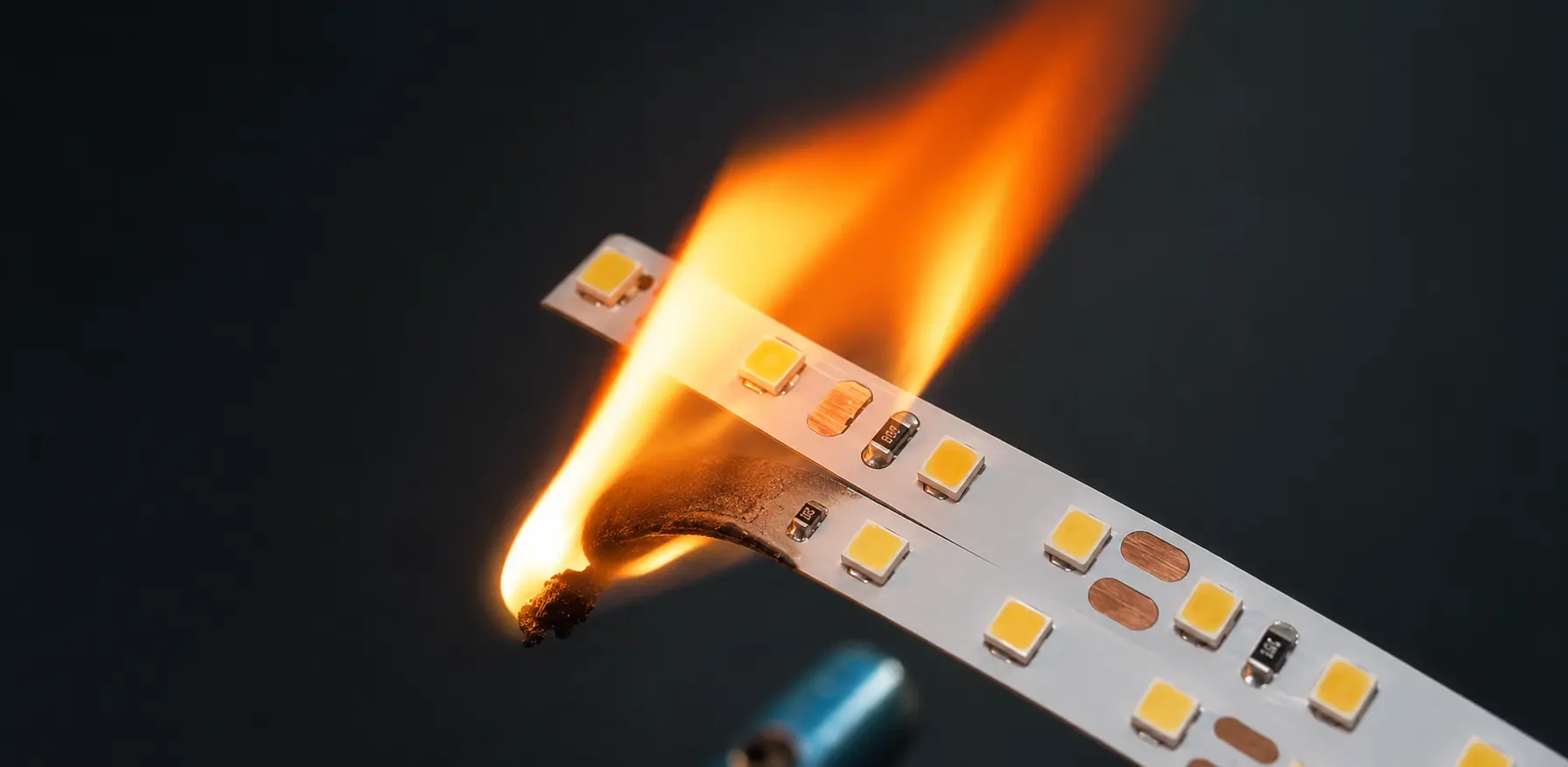
LED strip lights can cause a fire when the power supply, wiring, connectors, protection or installation method is incorrect.
The LED chips themselves are rarely the original ignition source. Most dangerous failures begin elsewhere:
- A loose connector creates concentrated heat.
- An undersized wire carries more current than intended.
- A large power supply feeds an unprotected short circuit.
- A tightly coiled strip traps heat.
- A driver operates above its thermal limit.
- A damaged PCB contacts combustible material.
A correctly specified and installed LED strip system should not ignite during normal operation. But low voltage and low LED temperature do not mean zero fire risk.
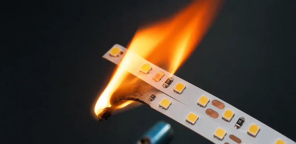
A 12V lighting system can carry more than 20A. A poor connection can turn a small plastic connector into a localized heater. Waterproof encapsulation can protect against moisture while simultaneously making heat harder to remove.
The entire system must be evaluated:
Power supply → controller → distribution wiring → connectors → LED strip → mounting surface
Quick Answer: Can LED Strip Lights Catch Fire?
Yes, but usually because of an electrical fault, unsuitable component or installation error rather than normal LED operation.
The ten most important risks are:
- Wrong voltage or driver type
- Overloaded or poorly ventilated power supply
- Undersized wires
- Loose connectors or poor solder joints
- Missing output-branch protection
- Overloaded controllers and common conductors
- Operating the strip while coiled or overlapped
- Inadequate heat dissipation
- Physical damage, incorrect cutting or sharp bending
- Waterproofing, moisture and enclosed installations
A safe strip cannot compensate for an unsafe driver, connector or wiring system.
How Does an LED Strip Fire Start?
A fire normally requires:
- A heat source
- Combustible material
- Oxygen
In an LED strip installation, the heat source may be:
- Electrical resistance
- A short circuit
- An overloaded component
- An electrical arc
- An internally failed driver
- Heat accumulated in an enclosed space
Possible combustible materials include:
- Connector housings
- Cable insulation
- Adhesive tape
- Plastic diffusers
- Wood
- MDF
- Fabric
- Dust
- Insulation material
- Nearby decorative finishes
The strip does not need to reach an abnormal temperature across its entire length. A tiny fault location can become much hotter than the surrounding installation.
Normal Heat, Overheating and Fire Risk
| Condition | Meaning | Required response |
|---|---|---|
| Warm strip or profile | Normal electrical losses are producing heat | Confirm temperature is within the product limits |
| One location hotter than the rest | Contact, component or thermal-path problem may exist | Switch off and investigate |
| Soft adhesive or deformed plastic | Materials have experienced excessive heat | Stop using the system |
| Brown marks or burnt odor | Abnormal electrical or material degradation | Disconnect power immediately |
| Smoke or active burning | Serious fault or ignition | Isolate power if safe and contact emergency services |
| Repeated fuse or breaker operation | Overload, short circuit or equipment failure | Do not repeatedly reset without diagnosis |
There is no universal “safe to touch” temperature. The permitted temperature depends on the LED package, PCB, connector, cable, adhesive, profile and nearby materials.
Why Low Voltage Can Still Produce Dangerous Heat
Electrical power is:
Power = Voltage × Current
Or:
P = V × I
Therefore:
Current = Power ÷ Voltage
For a 120W installation:
| Voltage | Nominal current |
| 12V | 10A |
| 24V | 5A |
| 48V | 2.5A |
The same power at 12V requires four times the current of a 48V system.
Higher current increases:
- Cable loss
- Connector heating
- PCB conductor loading
- Voltage drop
- Fault-current concerns
- Required conductor size
Low voltage can reduce shock risk when used within an appropriate power-limited system. It does not eliminate fire risk.
Why a Small Resistance Can Become a Serious Hotspot
Resistive heat is:
Power loss = Current² × Resistance
Or:
P loss = I²R
Assume a loose or contaminated connection has a resistance of 0.05Ω:
| Current | Heat produced at the connection |
| 2A | 0.2W |
| 5A | 1.25W |
| 10A | 5W |
| 15A | 11.25W |
More than 11W concentrated in a small connector can rapidly damage plastic, insulation and nearby material.
The rest of the LED strip may remain at a normal temperature while the connector becomes dangerous.
Using Voltage Drop to Detect a Bad Connection
A technician can evaluate a loaded connection by measuring the voltage across it.
Power dissipated at the joint is:
Joint heat = Current × Voltage across joint
Or:
P joint = I × ΔV
Example:
- Branch current: 8A
- Voltage measured across connector: 0.25V
8A × 0.25V = 2W
That connector is dissipating approximately 2W locally.
A healthy connection should have a very small voltage drop. The acceptable result depends on the connector design, current and manufacturer data.
Measurements on energized systems should be performed only by qualified personnel using suitable equipment.
Risk 1: Wrong Voltage or Driver Type
Most flexible LED strips use a constant-voltage DC power supply.
Common strip voltages include:
- 5V
- 12V
- 24V
- 36V
- 48V
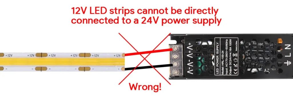
Connecting a 12V strip to a 24V supply can rapidly overdrive:
- LEDs
- Resistors
- Current-regulating ICs
- PCB traces
- Connectors
The excessive current may damage the strip before the upstream breaker operates.
Constant Voltage vs Constant Current
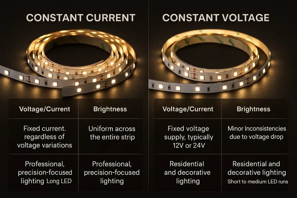
A conventional LED strip commonly requires a constant-voltage driver.
Some LED modules and specialty products require constant-current operation.
Using the wrong type can cause:
- Overcurrent
- Incorrect dimming
- Unstable operation
- Component overheating
- Premature failure
Always confirm:
- Output voltage
- Constant-voltage or constant-current mode
- Maximum output current
- Dimming method
- Polarity
Mains-Voltage Strips Are a Different Product Category
A 110V or 230V LED strip is not a higher-voltage version of a 12V or 24V strip.
It uses a different electrical architecture and requires suitable:
- Rectifier or power plug
- Mains-rated cable
- Insulation
- End caps
- Connectors
- Touch protection
- Cutting procedure
Never mix low-voltage accessories with a mains-voltage strip.
Xmart’s 110V/230V LED strip range is a separate product category from its constant-voltage low-voltage strips.
Power-Supply Protection Functions
Depending on the application, a suitable driver may need:
- Short-circuit protection
- Overcurrent protection
- Overvoltage protection
- Overtemperature protection
- Input-surge protection
- Electrical isolation
Protection behavior also matters.
A driver may respond to a short circuit by:
- Limiting current
- Shutting down and latching off
- Entering hiccup mode
- Repeatedly attempting to restart
Repeated restart pulses can continue delivering energy into some faults. Do not assume that “short-circuit protected” means every downstream wire and connector is automatically protected.
Risk 2: Overloaded or Poorly Ventilated Power Supply
Driver sizing starts with the maximum real load.
For a single-color strip:
Total strip load = Length × Watts per meter
Example:
15m × 12W/m = 180W
For RGB, RGBW, RGBCCT and tunable-white strips, confirm whether the stated W/m represents:
- One channel
- All channels
- A limited combined load
- A controller-restricted operating mode
Do not assume every channel can operate at maximum output simultaneously.
Why a Fixed 20% Margin Is Not Always Enough
Many projects use an initial rule of operating the driver at no more than approximately 80% of its nameplate power.
That can be a useful planning assumption, but final selection must follow the driver manufacturer’s data.
Available output can be affected by:
- Ambient temperature
- Input voltage
- Enclosure
- Mounting orientation
- Ventilation
- Continuous operating duration
- Dimming method
- Driver derating curve
A driver rated for 200W in open air may not be able to deliver the same continuous power in a sealed ceiling cavity at elevated temperature.
Driver Heat Must Escape
Avoid:
- Covering the driver with insulation
- Mounting it beside another heat source
- Installing it in an undersized sealed box
- Blocking ventilation slots
- Mounting it on a heat-sensitive surface without evaluation
- Operating above the rated ambient temperature
Keep drivers accessible for inspection and replacement whenever possible.
Xmart’s LED driver range includes constant-voltage, dimmable and IP-rated options. Voltage, load, ambient conditions and control method must be matched to the exact installation.
Can a Bigger Power Supply Push Too Much Power?
A regulated constant-voltage supply does not normally force its full rated wattage into the strip. The load draws current according to its circuit.
However, an oversized supply can make more current available during a fault.
A 600W driver and a 60W driver may both operate a 40W branch normally. Their available fault current and protection behavior can be very different.
Larger supplies increase the importance of:
- Output branch protection
- Wire size
- Connector ratings
- Distribution blocks
- Fault analysis
A larger driver does not fix voltage drop.
Risk 3: Undersized DC Wires
Wire selection must consider:
- Current
- Cable length
- Voltage drop
- Ambient temperature
- Cable bundling
- Insulation temperature rating
- Installation inside conduits or enclosures
- Applicable electrical requirements
An undersized cable can still make the strip light up. That does not mean the cable is safe.
Possible warning signs include:
- Warm cable
- Soft insulation
- Voltage drop
- Dim strip ends
- Discolored terminals
- Burning smell
- Intermittent operation
Why Watts Alone Cannot Size a Wire
A 100W load represents:
- 8.33A at 12V
- 4.17A at 24V
- 2.08A at 48V
A cable should be sized by current and installation conditions, not by an incomplete “wattage capacity” description.
The Voltage-Drop Workaround Can Create Another Risk
Installers sometimes increase the power-supply voltage adjustment to compensate for voltage drop.
Excessively increasing the driver voltage can overvoltage the beginning of the strip while only partially correcting the far end.
The correct solutions include:
- Larger wire
- Shorter cable
- Higher system voltage
- Additional feed points
- Center feeding
- Correctly designed power injection
Do not use excessive output-voltage adjustment as a substitute for proper distribution.
Risk 4: Loose Connectors, Poor Soldering and DC Arcing
Connections are frequent fault points because large current passes through a small contact area.
High resistance can result from:
- Connector not fully closed
- Incorrect PCB thickness
- Misaligned copper pads
- Wrong wire size
- Partially cut wire strands
- Oxidized copper
- Cold solder joint
- Mechanical movement
- Thermal cycling
- Moisture
- Connector used above its current rating
Why DC Connections Need Care
Alternating current passes through zero twice during each cycle, which can help extinguish some arcs.
Direct current does not have the same natural zero crossing. Whether an arc continues depends on voltage, available current, distance and circuit characteristics.
Low-voltage LED strip systems are less likely to sustain a long arc than high-voltage DC systems, but intermittent contact can still cause:
- Micro-arcing
- Surface damage
- Carbonized material
- Increasing resistance
- Local overheating
A loose connection may deteriorate progressively rather than fail immediately.
Solderless Connectors Are Not Automatically Safer
A solderless connector can be reliable only when it matches:
- PCB width
- PCB thickness
- Pin count
- Copper-pad layout
- Strip current
- Wire size
- Waterproof construction
Xmart’s LED strip connector range includes connectors for SMD, COB and multichannel strips. The current and environmental rating should be confirmed for the exact product.
For high-current or inaccessible projects, factory-installed cables or qualified soldered connections may offer better long-term control.
Connection Inspection
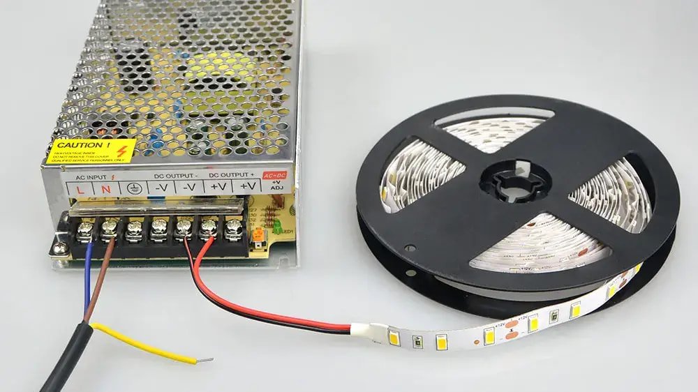
After thermal stabilization, check for:
- Temperature higher than adjacent cable
- Discoloration
- Melted or softened plastic
- Flicker when the cable moves
- Measurable voltage across the connection
- Loose mechanical fit
- Odor
- Crackling or buzzing
A hot connector should be investigated even when the strip continues operating.
Risk 5: Missing Output-Branch Protection
A large power supply may feed several small parallel branches.
Consider a 400W, 24V supply:
400W ÷ 24V = 16.7A
If one small branch uses wire and connectors intended for only a few amperes, that branch may be exposed to much more fault current than its components can safely carry.
The mains breaker primarily protects upstream building wiring. It may not provide suitable protection for every low-voltage branch.
Appropriate output protection can limit energy delivered into:
- Shorted PCB traces
- Crushed cables
- Failed connectors
- Incorrect field joints
- Damaged controllers
Protection should be selected according to:
- Branch wire
- Connector
- Controller
- Expected operating current
- Driver protection behavior
- Applicable requirements
Do not copy a fuse value from another project. Protective-device selection should be coordinated with the actual conductors and equipment.
Class 2 Reduces Risk but Does Not Eliminate It
In North American installations, a Class 2 power source limits available output energy according to the applicable safety requirements.
This can reduce fire and electric-shock risk.
It does not remove the need for:
- Secure connections
- Suitable conductors
- Correct installation
- Required markings
- Manufacturer instructions
- Appropriate downstream components
UL 2108 includes requirements relevant to low-voltage lighting systems and field-cuttable flexible LED products.
Risk 6: Controller, Dimmer and Common-Conductor Overload
A controller can overheat even when the driver and strip are correctly sized.
Check both:
- Maximum current per channel
- Maximum total controller current
A controller advertised as 20A may not permit every output channel to carry the same share simultaneously.
Common Positive and Common Negative Conductors
Many analog RGB, RGBW and tunable-white strips use a common conductor.
That conductor may carry the combined return or supply current of several active channels.
For example, individual color wires may each carry moderate current while the common positive conductor carries their total.
Possible risks include:
- Common terminal overheating
- Undersized common wire
- Distribution-block overload
- PCB input-pad heating
- Connector overload
Size the common conductor and terminal for the maximum permitted combined load.
Dimming Does Not Always Reduce Component Stress as Expected
At 50% PWM brightness, the average current is reduced, but the instantaneous current during each on-period may still be near full channel current.
Connectors, terminals and switching components must be suitable for the peak and RMS conditions defined by the controller and load.
Signal Amplifiers and Repeaters
RGB and tunable-white systems may use amplifiers to extend total power.
Each amplifier requires correct:
- Power input
- Branch wiring
- Output current
- Polarity
- Ground reference
- Protection
- Cooling
Do not treat a signal amplifier as an unlimited-current distribution device.
Risk 7: Operating the Strip While Coiled or Overlapped
A full LED strip reel should not normally be operated at full output while tightly coiled unless the manufacturer explicitly permits it.
When coiled:
- Adjacent layers heat one another.
- Airflow is restricted.
- The reel core stores heat.
- Inner turns can become hotter than the visible surface.
- Waterproof encapsulation increases insulation.
The risk increases with:
- Higher watts per meter
- Longer reels
- COB strips
- High-density strips
- Waterproof products
- High ambient temperature
- Full-white operation on multichannel strips
Before a full-power test:
- Unroll the strip.
- Prevent overlap.
- Mount it on the intended surface or profile.
- Monitor the highest-temperature locations.
- Follow the manufacturer’s test instructions.
Why Overlapping Is Dangerous
Overlapping powered sections concentrates two thermal loads in one area.
It can also:
- Compress LEDs
- Damage solder joints
- Trap the adhesive
- Bring exposed pads together
- Create a local hotspot
Do not hide excess strip behind or underneath another powered section.
Cut and reconnect at the designated cut point.
Risk 8: Inadequate Heat Dissipation and Combustible Surfaces
Electrical input power that is not converted into light becomes heat.
The thermal path is approximately:
LED junction → LED package → PCB → adhesive → mounting surface → ambient air
Every layer adds thermal resistance.
Risk increases when:
- Watts per meter are high.
- The PCB is narrow.
- Copper weight is low.
- The strip is inside an enclosed cavity.
- Waterproof material surrounds the PCB.
- The mounting surface is thermally insulating.
- Several strips are installed side by side.
- Airflow is restricted.
- Ambient temperature is high.
Does Every LED Strip Need an Aluminum Profile?
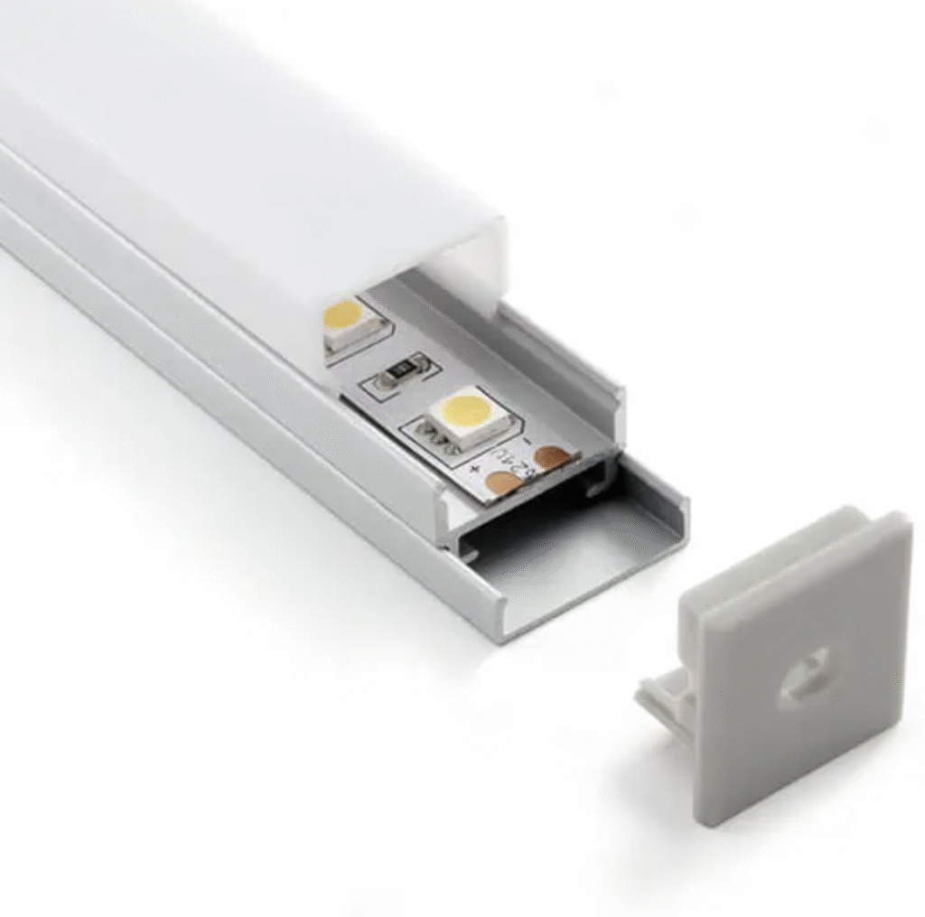
Not every low-power strip requires one.
However, aluminum profiles are strongly recommended for many professional medium- and high-power installations because they provide:
- Heat spreading
- Mechanical support
- A stable mounting surface
- Physical protection
- Optical diffusion
An aluminum profile is not a universal cure.
A small profile inside a sealed, insulated cavity can still become too hot.
Xmart’s LED aluminum profile range includes furniture and architectural profiles for different PCB widths and thermal loads.
Can LED Strip Be Installed on Wood?
It may be possible when:
- Product instructions allow it.
- Operating temperature has been verified.
- Power density is appropriate.
- The strip is securely mounted.
- Required clearances are maintained.
- Applicable regulations permit it.
Wood, MDF and many plastics do not spread heat as effectively as aluminum. They may also provide fuel if a local electrical fault occurs.
For furniture and cabinets, an aluminum profile often provides a more controlled installation.
Adhesive Tape Is Not a Heat Sink
Adhesive secures the strip. It does not replace a suitable thermal path.
Poor adhesion can allow the strip to:
- Detach
- Curl
- Overlap
- Contact nearby materials
- Lose thermal contact
Clean the mounting surface and use the specified mechanical support where required.
UL 94 Is Not a Complete-Product Fire Certification
UL 94 evaluates the flammability behavior of plastic materials under defined test conditions.
A UL 94 rating on:
- Connector plastic
- PCB substrate
- Diffuser
- Adhesive component
does not automatically certify the complete LED strip system as fireproof.
Ask which component was tested, to what classification and whether the rating applies to the final construction.
Risk 9: Physical Damage, Incorrect Cutting and Sharp Bending
Flexible LED strip is bendable, but it is not designed to be folded, crushed, stapled or pierced.
Damage can:
- Crack copper traces
- Expose conductors
- Short positive and negative rails
- Break solder joints
- Damage LED packages
- Separate waterproof encapsulation
Common errors include:
- Folding the strip at 90 degrees
- Driving a screw through the PCB
- Using metal staples
- Crushing the strip under a diffuser
- Pulling it by the cable
- Twisting a standard strip
- Cutting away from the marked line
- Leaving loose copper strands
- Allowing cut pads to touch metal
Safe Direction Changes
Use:
- Approved corner connectors
- Insulated wire jumpers
- Qualified soldered joints
- Zigzag LED strips
- Side-emitting products
- Purpose-built side-bending or 3D neon flex
Do not force a conventional strip into a geometry it was not designed to follow.
Cut Ends Must Be Insulated
Even in dry indoor installations, an unused cut end can expose positive and negative copper pads.
Prevent contact with:
- Aluminum profiles
- Screws
- Conductive debris
- Tools
- Other strip sections
Use the specified end insulation or sealing method.
Risk 10: Waterproofing, Moisture and Enclosed Installations
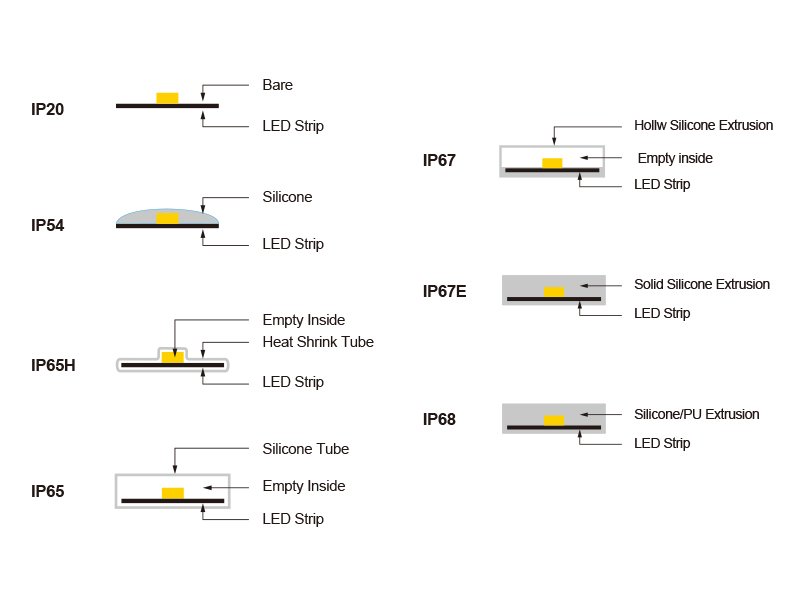
Waterproofing can reduce moisture ingress while making heat harder to remove.
Possible thermal problems include:
- Air gaps inside silicone tubes
- Encapsulation around the PCB
- Poor profile contact
- Thick polymer insulation
- Higher operating temperature
- Reduced airflow
The IP20 and IP67 versions of the same strip can have different thermal behavior.
Test the exact construction.
Moisture Can Cause Delayed Heating
Moisture does not always create a clean short circuit.
Long-term moisture can cause:
- Copper corrosion
- Increased contact resistance
- Leakage paths
- Dendritic growth
- Intermittent faults
- Connector degradation
A corroded connection can become a high-resistance hotspot.
This is why water exposure, connector sealing and drainage affect fire risk as well as reliability.
Enclosed Furniture and Ceiling Cavities
An enclosure can trap heat from:
- LED strip
- Driver
- Controller
- Adjacent equipment
Avoid placing all system components in one small unventilated cavity unless the assembly has been thermally evaluated.
Drivers should remain accessible and ventilated according to their instructions.
IP Rating Is Not a Thermal or Fire Rating
IP65, IP67 and IP68 describe ingress protection.
They do not define:
- Maximum power
- Maximum PCB temperature
- Thermal resistance
- Flame propagation
- Suitability for insulation contact
- Safe mounting surface
Ingress protection, thermal design and fire safety must be evaluated separately.
Power Injection: A Frequent Source of Hidden Risk
Power injection adds electrical feeds along a long strip to reduce voltage drop.
It is a valid engineering method, but it creates additional branches and joints.
Possible errors include:
- Reversed polarity
- Undersized injection wire
- Unprotected branch
- Connector overload
- PCB input-pad overload
- Exposed splice
- Incorrect grounding
- Connecting separate supply outputs together
Do not connect the positive outputs of separate power supplies unless the supplies and system are explicitly designed for parallel operation.
Addressable strips may require a common reference for data integrity. That requirement does not automatically authorize paralleling power-supply outputs.
Worked Example: A Safer 15-Meter Distribution Layout
Consider a 24V strip rated at 12W/m.
Total load:
15m × 12W/m = 180W
Total nominal current:
180W ÷ 24V = 7.5A
Poor preliminary layout
One driver feeds the entire 15m run through one small connector and the strip PCB.
Possible problems:
- 7.5A through the input connection
- Large voltage drop
- Heavy current in the first PCB section
- One fault path for the complete system
- Connector overheating
Better preliminary layout
Divide the installation into three 5m branches.
Each branch:
- Power: 5m × 12W/m = 60W
- Current: 60W ÷ 24V = 2.5A
The distribution becomes:
| Branch | Length | Power | Nominal current |
| 1 | 5m | 60W | 2.5A |
| 2 | 5m | 60W | 2.5A |
| 3 | 5m | 60W | 2.5A |
| Total | 15m | 180W | 7.5A |
Potential advantages include:
- Lower current per connector
- Lower voltage drop
- Easier wire sizing
- Easier fault isolation
- Opportunity for coordinated branch protection
This is an illustrative distribution concept, not a final wiring prescription. Cable sizes and protective devices must be selected for the actual installation.
Risk Priority Table
| Risk | Typical likelihood | Potential severity | Easy to detect visually? |
| Loose connector | High | High | Not always |
| Wrong voltage | Medium | High | Usually after damage |
| Undersized wire | Medium | High | Not before heating |
| Coiled operation | Medium | Medium–high | Yes |
| Driver overload | Medium | High | Sometimes |
| Missing branch protection | Common design omission | High during a fault | No |
| Controller overload | Medium | High | Not always |
| Physical PCB damage | Medium | High | Sometimes |
| Poor heat dissipation | High | Medium–high | Not without measurement |
| Moisture corrosion | Application-dependent | High over time | Often delayed |
The risks that are hardest to see—loose contacts, missing branch protection and internal corrosion—deserve particular attention.
How to Identify the Likely Failure Location
| Symptom | Possible cause |
| Driver repeatedly restarts | Overload, short circuit or thermal protection |
| One connector is hot | High contact resistance or overload |
| Entire cable is warm | Undersized conductor or excessive current |
| Strip input is much hotter than the end | High input current or PCB loading |
| Strip is hot only inside enclosure | Poor airflow or inadequate thermal path |
| One section flickers when moved | Cracked PCB or loose connection |
| RGB controller terminal is discolored | Channel or common-terminal overload |
| Fuse operates only at full white | Combined channel load too high |
| Waterproof strip shows green corrosion | Moisture ingress |
| Adhesive softens and strip falls | Excess temperature or unsuitable tape |
Symptoms can have multiple causes. Do not diagnose solely from one visual sign.
Certification and Documentation
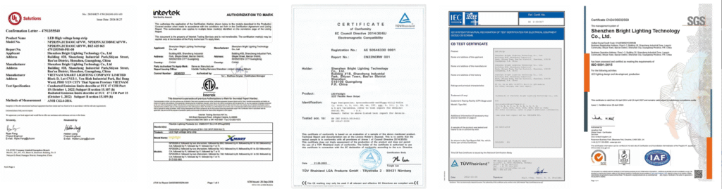
Requirements depend on the market and installation type.
Relevant North American standards may include:
- UL 2108 for low-voltage lighting systems
- UL 8750 for LED equipment used in lighting products
- UL 1310 for Class 2 power units
- Other standards for luminaires, signs, furniture or wet locations
Important distinctions:
- UL Listed and UL Recognized have different scopes.
- A certified LED package does not certify the complete strip.
- A certified driver does not approve field wiring.
- CE marking is not equivalent to UL or ETL third-party certification.
- RoHS addresses restricted substances, not fire protection.
- An IP rating is not a fire rating.
- A UL 94 material rating is not a complete-system approval.
Ask for documentation tied to the exact model, voltage, construction and intended use.
Warning Signs That Require Immediate Shutdown
Stop using the system if you detect:
- Smoke
- Burning smell
- Brown or black marks
- Melted connector
- Soft cable insulation
- Crackling
- Repeated flickering
- Driver repeatedly cycling
- Repeated fuse or breaker operation
- Water inside a connection
- One terminal much hotter than adjacent terminals
- Strip detaching and overlapping
- Deformed profile diffuser
Do not continue running the system to observe whether the fault becomes worse.
What to Do If the Strip Smokes or Burns
If it is safe:
- Disconnect power at the source or circuit breaker.
- Keep people away.
- Do not touch exposed conductors.
- Do not apply water to energized electrical equipment.
- Contact emergency services if fire or smoke continues.
- Have the entire system inspected before it is energized again.
Replacing only the visibly damaged strip may leave the original cause unchanged.
Professional Commissioning Procedure
1. Verify the bill of materials
Confirm:
- Strip voltage
- W/m
- Driver voltage and power
- Controller limits
- Connector model
- Wire size
- Branch protection
- Profile
- IP construction
2. Inspect before power is applied
Check:
- Polarity
- Loose wire strands
- Soldering
- Connector alignment
- Cut-end insulation
- PCB damage
- Overlap
- Bend radius
- Cable strain relief
3. Measure every branch
Record:
- Driver output voltage
- Branch current
- Strip input voltage
- End voltage
- Controller current
- Voltage across important joints
4. Test the maximum permitted operating condition
For RGBW and RGBCCT products, use the maximum approved combined-channel scene—not an arbitrary assumption that every channel may operate at 100%.
5. Allow temperatures to stabilize
Measure:
- Driver case
- Controller terminals
- Distribution block
- Branch connectors
- Strip input
- Strip PCB
- Aluminum profile
- Ambient temperature
6. Look for localized hotspots
Average temperature can look acceptable while one small connection is overheating.
A thermocouple or properly configured thermal camera should be used consistently. Shiny aluminum, white PCB and silicone can display inaccurate apparent temperatures when emissivity is not considered.
7. Document the approved installation
Keep:
- Wiring diagram
- Driver and controller models
- Wire sizes
- Protection details
- Measured currents
- Stabilized temperatures
- Installation photographs
- Product labels
- Test date
Documentation makes later maintenance and repeated projects safer.
Procurement Checklist
Before purchasing an LED strip system, request:
- Strip voltage
- Constant-voltage or constant-current requirement
- Watts per meter
- Maximum channel load
- Maximum single-feed length
- PCB width and copper construction
- Maximum permitted PCB temperature
- Required mounting method
- Driver protection behavior
- Driver derating curve
- Controller total current
- Controller current per channel
- Common-conductor rating
- Connector current rating
- Recommended wire range
- Power-injection diagram
- Output-branch protection guidance
- Exact certification model
- IP construction
- Thermal test conditions
Common Myths
LEDs are cool, so LED strips cannot cause fires
False. Drivers, connectors, cables and PCB traces can overheat during faults.
Low voltage means no fire risk
False. Low-voltage systems can carry high current.
A bigger power supply is safer
Not automatically. It can increase available fault current.
The mains breaker protects every LED wire
Not necessarily. Small downstream branches may require coordinated protection.
If a connector works, it is safe
False. A high-resistance connector can work while heating.
A fuse protects the LED strip from every problem
False. It cannot correct poor heat dissipation, wrong voltage or an unsuitable driver.
Aluminum profiles prevent all overheating
False. Profile size, thermal contact, airflow and ambient temperature still matter.
More LEDs per meter always means more heat
False. Watts per meter and efficacy are more important.
Waterproof strips cannot short circuit
False. Cut ends, connectors, mechanical damage and corrosion remain possible failure points.
CE, RoHS or IP68 means fire-safe
False. Each marking covers a different scope.
Final Recommendation
LED strip lights are not inherently likely to start a fire when they are correctly specified, protected and installed.
The most important fire risks come from:
- Excess voltage
- High current
- Poor connections
- Inadequate protection
- Trapped heat
- Physical damage
- Moisture-related corrosion
Design the complete electrical path rather than selecting the strip in isolation.
Calculate the load, divide large installations into controlled branches, match the driver and controller, use properly rated wires and connectors, provide thermal management and test the completed installation at its worst permitted operating condition.
The safest LED strip is not simply the product with the lowest wattage or the most certification logos.
It is the product used within a system whose voltage, current, fault protection, temperature and installation conditions have all been verified.
Frequently Asked Questions
Can LED strip lights catch fire?
Yes. Incorrect voltage, poor power supplies, undersized wires, loose connections, short circuits and trapped heat can create a fire risk.
Are 12V LED strips a fire risk?
They can be. A 12V system carries relatively high current for a given power, so wire and connector sizing are important.
Is 24V safer than 12V?
A 24V system carries half the current at the same power, reducing some conductor and connector losses. Safety still depends on the complete design.
Can LED strips be left on overnight?
Only when the complete system is rated, installed and thermally validated for continuous operation.
Is it normal for LED strips to become warm?
Yes. Some heat is normal. Burning odor, discoloration, deformation or an isolated hot connector is not.
How hot is too hot?
There is no universal surface-temperature limit. Use the maximum PCB, component, adhesive and ambient ratings for the exact product.
Do LED strips need aluminum profiles?
Many medium- and high-power strips benefit from them. Low-power products may not always require one if the installation instructions permit another mounting method.
Can LED strips be installed on wood?
They can be in properly evaluated applications, but aluminum profiles provide better heat spreading and mechanical protection.
Can I power an LED strip while it is on the reel?
Do not operate a tightly coiled reel at full power unless the manufacturer specifically permits it.
Can a loose connector cause a fire?
Yes. A small contact resistance can produce several watts of heat at high current.
Does a larger power supply push too much current?
Not during normal constant-voltage operation, but it can provide more current during a fault.
Does a larger power supply fix voltage drop?
No. Use appropriate wires, feed points and voltage architecture.
Should every branch have a fuse?
Large multi-branch systems often require suitable output protection, but the exact design depends on the power source, wires, connectors and applicable requirements.
Can a controller overheat?
Yes. Per-channel, total-current and common-terminal limits must all be respected.
Can waterproof LED strips overheat?
Yes. Encapsulation can increase thermal resistance or create air gaps.
Can moisture create a fire risk?
Yes. Corrosion can raise contact resistance and create delayed localized heating.
What causes an LED driver to overheat?
Overload, insufficient ventilation, high ambient temperature, blocked airflow, wrong input conditions and component failure are common causes.
Does UL 94 mean the whole strip is fireproof?
No. UL 94 generally applies to the tested plastic material or component, not automatically to the complete installation.
What should I do if an LED connector is hot?
Switch off the system and inspect the connector, current, wire, alignment and contact resistance before re-energizing it.
Need Help Designing a Safer LED Strip System?
Xmart Lighting supports system-level LED strip selection for lighting brands, distributors, furniture manufacturers and commercial projects.
Project support can include:
- Voltage and wattage selection
- Constant-voltage driver matching
- Controller-current review
- Wire and connector matching
- Branch and power-injection planning
- Aluminum-profile selection
- Waterproof-construction selection
- Thermal test support
- Factory-installed cables
- OEM documentation
Explore Xmart’s LED driver options, LED strip connector range and LED aluminum profiles, or send the total length, W/m, control method, ambient temperature and installation drawing for a system-level recommendation.
For fault diagnosis, see Troubleshooting LED Strip Problems.