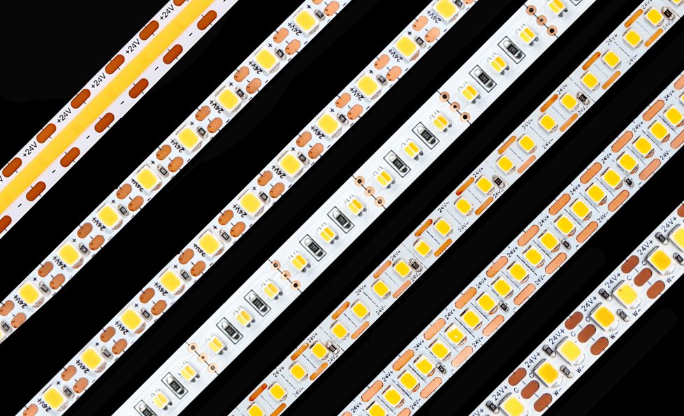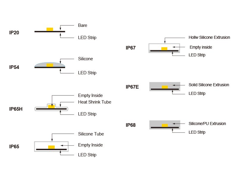
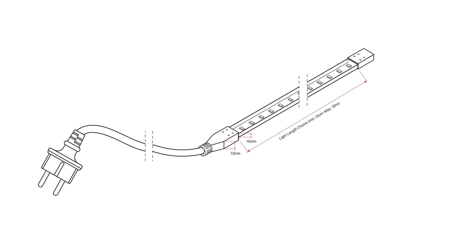
Driverless AC LED strips can operate over much longer distances than conventional 12V or 24V strips while eliminating multiple external LED drivers.
That sounds like an obvious improvement.
For building outlines, tunnels, temporary lighting, large signage and long architectural runs, fewer drivers and feed points can reduce:
- Installation labor
- Cable quantities
- Driver locations
- Power-injection points
- Junction boxes
- Maintenance access requirements
But “driverless” does not mean the LEDs operate without power-conversion electronics. It usually means that rectification, current limiting and protection functions have been moved onto the strip or into a compact mains connector instead of being housed in a separate external driver.
That changes the risk profile.
A driverless AC strip may simplify long-run wiring, but buyers must evaluate:
- Mains-voltage exposure
- Temporal light modulation, commonly called flicker
- Surge immunity
- Overvoltage behavior
- Insulation
- Cut and connection safety
- Power factor and harmonic current
- EMC
- Dimming compatibility
- Waterproof joints
- Operating temperature
- Product-specific certification
The correct comparison is not simply:
External driver versus no driver.
It is:
A centralized low-voltage power-conversion system versus a distributed or integrated mains-voltage power-conversion system.
Quick Answer: Are Driverless AC LED Strips a Good Choice?
Driverless AC LED strips can be a good choice when a project needs:
- Long continuous runs
- Fewer power-feed locations
- Reduced low-voltage cable current
- Simple on/off operation
- Outdoor outlines or large perimeter lighting
- Limited space for multiple external drivers
- Factory-finished plug-and-strip assemblies
They are usually less suitable when a project needs:
- Touch-safe exposed conductors
- Very short cutting intervals
- Frequent field modification
- Low-risk furniture or cabinet integration
- Smooth deep dimming
- Low temporal light modulation
- Camera-friendly operation
- Complex color control
- Easy compatibility with 0–10V, DALI, DMX or smart controls
- Installation inside conductive or user-accessible structures
A high-voltage AC strip should be treated as a mains-powered electrical product—not as a conventional low-voltage tape light with a different plug.
What “Driverless” Actually Means
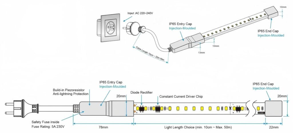
LEDs are semiconductor devices that require controlled current. They cannot normally be connected directly to an AC mains supply without supporting circuitry.
A driverless AC LED strip typically includes some combination of:
- Bridge rectifier
- Rectifier diodes
- Linear current-regulation ICs
- Resistors
- Capacitors
- Surge-suppression components
- Protection devices
- Repeated LED circuit sections
These components may be:
- Mounted along the flexible PCB
- Integrated into each cut section
- Located inside the power-entry plug
- Split between the strip and connector
The product has not eliminated the driver function. It has changed its physical location and circuit architecture.
A more accurate description is often:
- Integrated-driver AC LED strip
- Direct-mains LED strip
- High-voltage AC LED strip
- Driver-on-board LED strip
Driverless Does Not Automatically Mean Simpler Electronics
A low-voltage system may use one external driver supplying a relatively simple LED strip.
A driverless AC system may distribute rectification or current-control components across many repeating sections.
This can eliminate one large external driver while introducing:
- More onboard electronic components
- More mains-voltage PCB sections
- More insulation-critical interfaces
- More sensitivity to surge and mains variation
- Longer non-repairable or section-repair units
The useful question is not how many boxes are visible. It is how the complete electrical system is designed, protected, certified and serviced.
Why AC LED Strips Can Run Farther
For the same power, increasing voltage reduces current.
The simplified relationship is:
Current = power ÷ voltage
Consider a 20-meter strip rated at 10 W/m.
Total power:
20 m × 10 W/m = 200 W
Ignoring losses and power factor for this preliminary comparison:
At 24V DC
200 W ÷ 24V = 8.33 A
At 230V AC
200 W ÷ 230V = 0.87 A
The higher-voltage architecture carries much less current for the same nominal power.
Lower current can reduce:
- Conductor voltage drop
- Cable size requirements
- Connector current stress
- The number of power-injection points
- Power loss in long distribution cables
This is the main engineering reason high-voltage strips can support longer runs.
Higher Voltage Does Not Eliminate Every Run-Length Limit
The maximum permissible powered length can still be limited by:
- Strip conductor size
- Power-cord current rating
- Rectifier capacity
- Connector rating
- Protective-device rating
- Inrush current
- Operating temperature
- Voltage variation
- Power factor
- Harmonic current
- Certification scope
- Local circuit requirements
A “50-meter reel” is packaging information unless the supplier confirms that the complete 50 meters can be safely powered as one run under the stated voltage and installation conditions.
The specification should separate:
- Reel length
- Cut-unit length
- Maximum powered length
- Maximum circuit load
- Maximum series length
- Maximum length per connector
- Maximum length per protective device
Never Operate a Long Strip While It Is Coiled
A high-power strip operated on its reel can trap heat between layers.
Possible consequences include:
- Encapsulation softening
- PVC deformation
- Local overheating
- LED color shift
- Current-regulator stress
- Insulation damage
- Fire risk
Unroll the required test length and install it according to the manufacturer’s thermal instructions before continuous operation.
Driverless AC vs Low-Voltage DC LED Strips
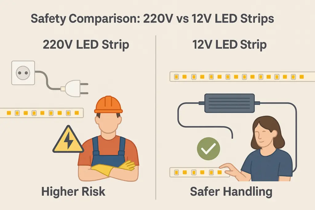
| Design factor | Driverless AC strip | Low-voltage DC strip |
|---|---|---|
| Typical supply architecture | Direct mains with integrated electronics | External constant-voltage driver |
| Common voltage | 110–120V or 220–240V AC | 12V, 24V or 48V DC |
| Practical run length | Generally longer | Generally shorter without additional feeds |
| Circuit current at equal power | Lower | Higher |
| Power injection | Less frequent | Often required on longer runs |
| External drivers | Fewer or none | Required |
| Electrical shock risk | Higher | Lower when supplied by an appropriate isolated SELV/Class 2 system |
| Cut interval | Usually longer | Usually shorter |
| Field termination | Safety-critical | More manageable, but still requires correct installation |
| Flicker risk | Architecture-dependent; can be significant | Mainly determined by driver and controller |
| Surge exposure | Directly exposed to mains transients | External driver may absorb or isolate part of the stress |
| Dimming | Product-specific and often limited | Wide choice of matched drivers and controllers |
| Repair | Larger sections may need replacement | Shorter strip sections may be replaceable |
| Control options | Usually basic | Broad PWM, DALI, 0–10V, DMX and smart-control options |
| Furniture integration | Usually unsuitable | Common application |
| Long outdoor outlines | Often practical when correctly certified | Possible but may need more drivers and feeds |
Neither architecture is universally better.
The decision depends on which problem is more important: long-run distribution or low-voltage flexibility and control.
Risk 1: Flicker and Temporal Light Modulation
Flicker is one of the most important differences between driverless AC products.
Why Rectified AC Can Produce 100Hz or 120Hz Modulation
The mains supply changes polarity:
- 50 times per second in a 50Hz system
- 60 times per second in a 60Hz system
A full-wave rectifier uses both halves of the AC waveform. Without adequate current smoothing, the LED light output can rise and fall twice per mains cycle:
- Approximately 100Hz on a 50Hz supply
- Approximately 120Hz on a 60Hz supply
A half-wave or differently controlled circuit can produce other waveform characteristics, including modulation at the mains frequency.
Because LEDs respond rapidly to current, they can reproduce these variations more directly than light sources with greater thermal or phosphor persistence.
The U.S. Department of Energy’s review notes that early low-cost driverless or AC-LED products could produce noticeable 60Hz or 120Hz modulation, although improved AC-LED circuit designs are available. See the DOE review of temporal light modulation.
Why Flicker May Not Be Obvious During a Sample Review
A strip can appear steady when viewed directly but reveal temporal light artifacts when:
- The observer moves their eyes
- An object moves through the light
- A reflective tool rotates
- Machinery operates
- A camera records the scene
- The light is dimmed
- The surrounding area is dark
- Multiple light sources interact
Possible effects include:
- Direct visible flicker
- Stroboscopic effect
- Phantom-array effect
- Camera banding
- Uneven slow-motion video
- Visual discomfort for some occupants
The DOE flicker research program explains that modulation frequency alone is insufficient; waveform, modulation depth, duty cycle and application all affect visibility.
Capacitors Can Reduce Flicker—but Create Trade-Offs
A manufacturer may add smoothing capacitance or use more advanced current regulation to reduce light-output modulation.
Possible trade-offs include:
- Larger components
- More heat
- Higher inrush current
- Reduced power factor
- Additional failure points
- Less PCB flexibility
- Shorter cut units becoming difficult
- Higher cost
A technically better design must balance:
- Modulation
- Power factor
- harmonic current
- Inrush
- Surge protection
- Temperature
- Component life
“Flicker-free” should therefore be supported by measured data, not only by the presence of a capacitor or an anti-flicker marketing label.
Which Flicker Data Should Buyers Request?
Request:
- Light-output waveform
- Fundamental modulation frequency
- Modulation depth
- Percent flicker, if provided
- Flicker index, if provided
- PstLM
- SVM
- Test voltage and frequency
- Full-output result
- Dimming results
- Test temperature
- Measurement method
No single flicker metric fully describes every visual effect.
PstLM is commonly used to assess short-term flicker perception, while SVM relates to the visibility of stroboscopic effects. Applicable limits depend on the product, market and project requirement.
Test at Both 50Hz and 60Hz Where Relevant
An export product may be sold into both:
- 220–240V, 50Hz markets
- 110–120V, 60Hz markets
The circuit and optical waveform should be validated for the exact rated supply.
Do not assume that a result measured at 230V/50Hz represents performance at 120V/60Hz.
Camera Projects Need Separate Testing
For studios, retail displays, sports facilities, machine vision and security-camera areas, test:
- Normal frame rates
- High frame rates
- Expected shutter speeds
- Dimming levels
- Moving subjects
- Actual camera equipment where possible
A phone-camera test can reveal obvious banding, but it is not a substitute for an instrumented temporal light modulation report.
Risk 2: Surge Exposure
A driverless AC strip is directly connected to the mains supply, so its onboard components can be exposed to switching and lightning-related transients.
Potential sources include:
- Nearby lightning activity
- Switching of motors
- Contactors
- Inductive loads
- Utility switching
- Long outdoor cable runs
- Building power disturbances
- Generator transfer
- Poor earthing or bonding
- Repeated small transients
What Surge Can Damage
Surges can affect:
- Rectifier diodes
- Linear current-regulator ICs
- LEDs
- Resistors
- Capacitors
- PCB insulation
- Connectors
- End seals
A severe event can cause immediate failure. Repeated lower-level transients can weaken components and produce delayed failure.
Common Protection Components
Depending on the design, protection may include:
- Fuse or fusible resistor
- Metal-oxide varistor
- Transient-voltage suppressor
- Inrush-limiting component
- Series impedance
- Thermal protection
- Coordinated external surge-protective device
The presence of one component does not establish a complete surge rating.
Protection effectiveness depends on:
- Component rating
- Location
- Energy capacity
- Line-to-line or line-to-earth path
- Earthing architecture
- Protective-device coordination
- Repetition rate
- End-of-life behavior
What a Surge Rating Should State
Do not accept only:
Built-in surge protection.
Request:
- Test method
- Test voltage
- Waveform
- Coupling mode
- Source impedance
- Number of positive and negative pulses
- Performance criterion
- Whether the product was powered
- Exact tested length
- Failure or degradation after testing
IEC 61000-4-5 defines a consistent method for evaluating equipment immunity to switching and lightning-related surge phenomena. It does not simulate a direct lightning strike.
A “4kV surge” statement without the test mode and setup is incomplete.
Product-Level and Building-Level Surge Protection Are Different
Onboard protection handles only the energy and waveform for which it was designed.
For exposed outdoor systems, the electrical designer may also require:
- Distribution-board SPD
- Local SPD
- Correct earthing
- Cable routing
- Separation from lightning-conductor systems
- Branch-circuit protection
A small PCB-mounted protection component should not be treated as a replacement for a coordinated building surge-protection design.
Risk 3: Mains-Voltage Electrical Safety
The biggest difference between a driverless AC strip and a 24V strip is not run length. It is the voltage accessible inside the product.
Many driverless AC strips are non-isolated mains circuits. Their internal conductors and LED circuit sections must be treated as hazardous live parts.
Insulation Is Part of the Safety System
Safety may depend on:
- Extruded PVC or silicone jacket
- Insulation thickness
- Material flammability
- Creepage and clearance
- Connector construction
- End caps
- Cable entry
- Adhesive or sealant
- Mechanical retention
- Strain relief
- Installation instructions
A small cut, puncture or poorly sealed connector can compromise the protection system.
Common High-Voltage Strip Hazards
- Exposed conductor at an incorrect cut
- Connector pins inserted off-center
- Damaged insulation from mounting clips
- Screws penetrating the strip
- Unsealed tail ends
- Reversed or incompatible power connectors
- Field repairs using unapproved components
- Sharp aluminum-profile edges
- Cable-entry pullout
- Water entering a mains-voltage connection
- Strip installed where occupants can touch it
- Strip energized during cutting
- Residual charge in capacitors after disconnection
Installation should be completed by appropriately qualified personnel in accordance with the product instructions and local electrical rules.
Disconnect the circuit, prevent unintended re-energization and verify the safe condition before cutting, connecting or inspecting the strip.
Low Voltage Is Not Automatically Safe Either
A 12V or 24V system can still overheat or cause fire if:
- Conductors are undersized
- Connectors are overloaded
- The driver is incorrectly protected
- Short-circuit current is high
- The strip is installed on combustible material
- Heat cannot escape
However, a correctly designed isolated SELV or Class 2 system substantially changes the electric-shock risk compared with a direct-mains strip.
Risk 4: Cutting and Field Connections
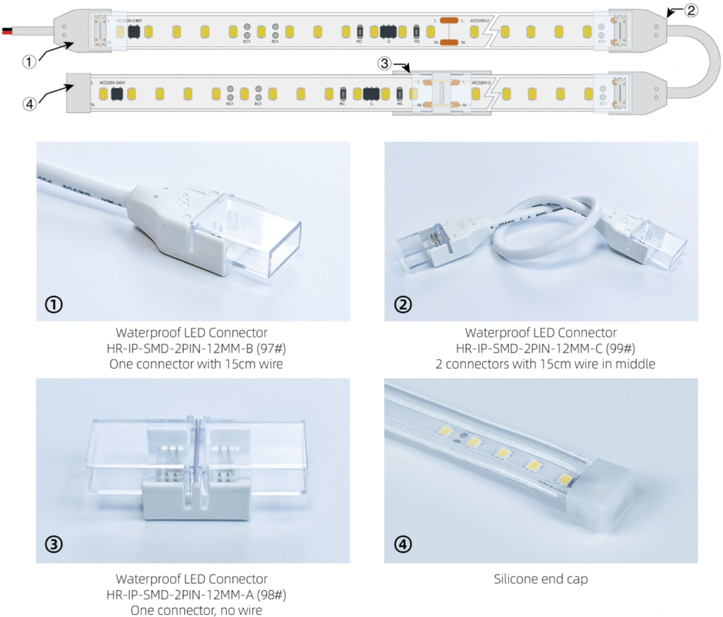
High-voltage strips usually have longer cut units because many LEDs and control components are arranged into a mains-voltage circuit section.
Typical cut units may be:
- 100 mm
- 250 mm
- 500 mm
- 1,000 mm
The exact value depends on voltage and circuit architecture.
A longer cut interval can create:
- Dark gaps at the ends of architectural runs
- Material waste
- Difficulty matching signage dimensions
- Poor fit around corners
- Larger replacement sections
- More complicated inventory
Cutting at the Mark Is Only the First Requirement
A safe field termination must also address:
- Correct connector
- Correct polarity or pin orientation where applicable
- Full conductor engagement
- Insulation
- End cap
- Sealant
- Cure time
- Strain relief
- Pull resistance
- Waterproof restoration
- Electrical test
A connector that powers the strip is not necessarily a safe or waterproof connector.
Does Field Sealing Restore the Original IP Rating?
Not automatically.
The factory IP report may cover:
- A molded factory end
- A specific cable
- A controlled sealant process
- A defined cure condition
A field-cut end assembled with glue may not be covered by the same evidence.
For outdoor and public installations, consider:
- Factory-finished lengths
- Molded power entries
- Molded end caps
- Tested repair kits
- Documented installer training
- Post-installation inspection
Risk 5: Heat and Fire Performance
Driverless AC strips contain LEDs and power-conversion components along the flexible circuit.
Heat can come from:
- LEDs
- Current-regulation ICs
- Rectifiers
- Resistors
- Surge components
- Poor connections
- Voltage variation
- Encapsulation
- Coiled operation
Local Hot Spots Matter
Average strip temperature can appear acceptable while one small component operates much hotter.
Measure:
- LED area
- Rectifier or regulator area
- Connector
- Power-entry point
- End of run
- Overlap or bend
- Enclosed profile
- Worst-case ambient location
Thermal testing should use:
- Maximum rated voltage
- Maximum powered length
- Declared mounting condition
- Worst-case ambient temperature
- Stabilized operation
- Applicable abnormal conditions
Encapsulation Can Trap Heat
A thick PVC or silicone jacket provides insulation and environmental protection but can also restrict heat transfer.
The same strip may operate differently when:
- Suspended in air
- Mounted with clips
- Installed in a plastic channel
- Installed in an aluminum profile
- Placed against wood
- Enclosed behind signage
- Exposed to solar heating
Do not use a free-air temperature test to approve a tightly enclosed project.
Risk 6: Power Factor, Harmonics and EMC
Removing the external driver does not remove power-quality requirements.
A driverless AC strip can draw a current waveform that differs significantly from a simple resistive load.
Relevant characteristics include:
- Power factor
- Total harmonic distortion
- Conducted emissions
- Radiated emissions
- Surge immunity
- Electrical fast transient immunity
- Electrostatic-discharge immunity
- Voltage-dip behavior
- Inrush current
These issues become more important when many meters are installed on one project.
Why One Short Sample Can Be Misleading
A one-meter sample may have acceptable input characteristics. A large installation can produce:
- Higher aggregate harmonic current
- Larger inrush
- Greater neutral loading in some systems
- More electromagnetic interference
- Different protective-device behavior
The electrical designer should evaluate the connected load at project scale.
IEC 61547 addresses EMC immunity requirements for lighting equipment within its scope. Emissions and other requirements must also be checked for the target market and exact product category.
Risk 7: Dimming May Be More Limited Than Expected
A low-voltage strip can be paired with a wide range of:
- PWM controllers
- DALI drivers
- 0–10V drivers
- DMX decoders
- Zigbee or Bluetooth controllers
- Matter-compatible control devices
A driverless AC strip usually requires a control device specifically compatible with its onboard electronics.
Potential problems include:
- Minimum-load instability
- Dropout at low dimming levels
- Flicker
- Flashing when switched off
- Incomplete turn-off
- Audible noise
- Uneven section brightness
- Increased modulation
- Dimmer overheating
- Limited dimming range
“TRIAC dimmable” is not a complete compatibility statement.
Request:
- Approved dimmer list
- Leading-edge or trailing-edge compatibility
- Minimum and maximum load
- Minimum stable dimming level
- Flicker data at multiple dimming points
- Off-state behavior
- Maximum circuit length per dimmer
- Test voltage and frequency
If smooth architectural dimming is a primary requirement, a low-voltage strip with a matched quality driver may be the more controllable solution.
Does Eliminating the External Driver Improve Reliability?
Sometimes—but not always.
Potential Reliability Advantages
- Fewer external boxes
- Fewer driver-access locations
- Fewer low-voltage feed circuits
- Reduced connector count in long installations
- Simpler stock and installation planning
Potential Reliability Disadvantages
- Mains stress reaches onboard electronics
- Surge protection space is limited
- Heat-generating components are distributed along the strip
- One failed section may interrupt or visibly damage part of a long run
- Repair occurs at mains-voltage interfaces
- Encapsulation can make component repair impractical
- Internal components may not be individually replaceable
A separate driver is replaceable as one service component. Integrated electronics can reduce external service points but make the luminous product itself the replaceable power-conversion component.
The correct reliability comparison should include:
- Failure mode
- Failed-section length
- Access time
- Replacement method
- Spare-parts strategy
- Connector resealing
- Labor
- Downtime
- Certification impact after repair
Installation Cost: Fewer Drivers Does Not Always Mean Lower Total Cost
Driverless AC strips can reduce:
- Driver quantity
- Driver enclosures
- Secondary cable
- Power injection
- Installation time
But the project may require additional spending on:
- Certified mains connectors
- Factory-finished lengths
- Branch protection
- RCD/GFCI protection where required
- Surge-protective devices
- Qualified electrical labor
- Mechanical guarding
- Waterproof junctions
- Safety inspection
- More expensive replacement sections
Compare Complete Installed Cost
Use:
Installed cost = product + power entry + protection + connectors + cable + labor + testing + access + expected maintenance
Do not compare only:
- AC strip price per meter
- DC strip price plus driver
A low-cost driverless strip with poor flicker, weak surge immunity or uncertified field connectors can become the more expensive system after installation and maintenance.
When Driverless AC Strips Make Sense
They may be practical for:
- Long building outlines
- Bridges and large façades
- Tunnel accent lighting
- Long canopy edges
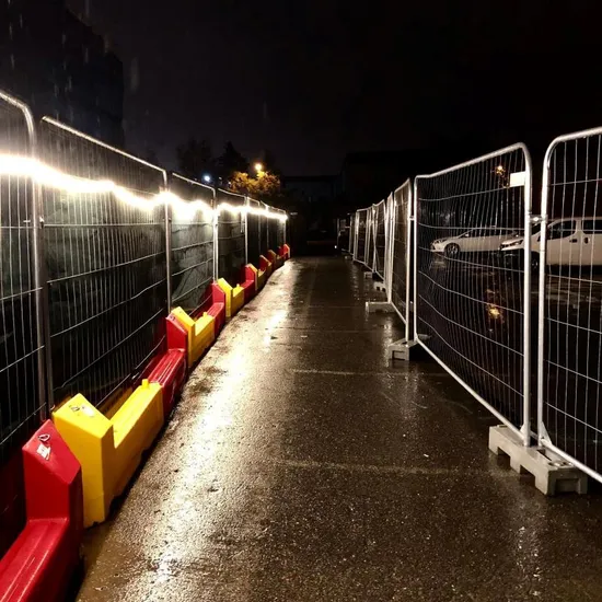
- Temporary construction lighting
- Large signage perimeters
- Long non-dimmed commercial runs
- Installations with limited driver locations
- Factory-finished outdoor assemblies
They are most suitable when:
- The strip cannot be touched during normal use
- The run is long enough to justify the architecture
- On/off control is sufficient
- Factory termination is possible
- Product-specific certification is available
- Maintenance teams understand the mains-voltage system
When Low-Voltage DC Is Usually the Better Choice
Prefer 12V, 24V or 48V DC when the project involves:
- Furniture
- Cabinets
- Shelves
- Handrails
- Bathrooms
- Short custom lengths
- Frequent field cutting
- User-accessible locations
- Detailed dimming
- Tunable white
- RGBW or RGBCCT
- Addressable control
- DALI
- 0–10V
- DMX
- Smart-home integration
- Camera-critical environments
For longer runs that still require low-voltage architecture, a 36V or 48V LED strip may provide a useful middle path between 24V DC and direct mains.
Certification: Verify the Exact Product, Not the Supplier Logo
Applicable standards depend on:
- Target country
- Product construction
- Supply voltage
- Indoor or outdoor use
- Portable or permanently installed use
- Whether the product is considered a module, rope light or luminaire
- Connection method
- Intended application
Potential references can include:
- UL 2388 for flexible lighting products in applicable North American evaluations
- IEC 60598-2-21 for rope lights or sealed lighting chains within its scope
- IEC 60598-1 for relevant luminaire requirements
- IEC 62031:2026 for LED module safety within its scope
- IEC 61547 for lighting-equipment EMC immunity
- IEC 61000-4-5 for surge-immunity test methodology
- IEC 60529 for ingress protection
- Market-specific EMC, hazardous-substance and energy requirements
IEC 62031:2026 covers safety requirements for applicable LED modules operating on AC supplies up to 1,000V and DC supplies up to 1,500V. The exact classification of a flexible AC product should be confirmed with the certification body.
CE, RoHS and Safety Certification Are Not the Same
- CE is a conformity marking based on applicable EU legislation and assessment.
- RoHS restricts specified hazardous substances.
- CB documentation supports conformity assessment against stated IEC standards.
- UL or ETL certification relates to compliance with the standard and scope identified in the listing.
A RoHS-compliant strip is not automatically electrically safe.
A CE mark without the declaration, applicable standards and technical file is not enough for a professional product review.
A certification for one voltage or connector does not automatically cover every custom version.
How to Evaluate an LED Strip Manufacturer

Choosing an LED strip manufacturer for a driverless AC project requires a different audit from buying a standard 24V strip.
Ask whether the manufacturer controls or verifies:
- PCB working voltage
- Insulation construction
- Creepage and clearance
- Rectifier and regulator ratings
- Surge-protection design
- Encapsulation thickness
- Material flammability
- Connector insertion
- Cable strain relief
- End-cap sealing
- Thermal hot spots
- Flicker waveform
- Power factor
- EMC
- Production hipot or dielectric testing
- Product traceability
A top LED strip manufacturer should be able to provide more than a reel sample and a certificate logo. It should be able to connect the exact BOM, voltage, plug, cable, connector, cut unit and waterproof construction to the relevant test evidence.
Manufacturing Questions
- Is the circuit resistor-limited, IC-regulated or a hybrid?
- Where is rectification performed?
- What happens if one LED fails open?
- What happens if one LED fails short?
- Is each cut section independently regulated?
- What is the maximum component temperature?
- Which surge components are used?
- Is there a fuse or fusible element?
- How is insulation thickness controlled?
- How are connectors and end caps inspected?
- Is dielectric-strength testing performed on production units?
- Are critical components controlled against substitution?
Required Product Test
| Test category | Data to request |
| Electrical input | Voltage range, frequency, watts/m, current, power factor, THD |
| Run length | Maximum powered length, test voltage, brightness variation |
| Flicker | Waveform, frequency, modulation, PstLM, SVM |
| Surge | Test method, level, coupling mode, pulse count, result |
| EMC | Immunity and emissions reports for target market |
| Thermal | Maximum-length test, component hot spots, ambient, mounting |
| Abnormal operation | Open/short section behavior, overvoltage response |
| Safety | Applicable standard, certificate, model scope |
| Insulation | Dielectric, insulation resistance, material construction |
| Fire | Material and abnormal-temperature evidence |
| Ingress | Exact IP test, connector and end-cap configuration |
| Mechanical | Bend, pull, strain relief, clip and connector tests |
| Dimming | Approved dimmers, range, flicker at dimmed levels |
| Production | Traceability, hipot test, aging and inspection procedure |
Driverless AC Strip RFQ Template
Include the following in a supplier request.
Project Information
- Target country
- Supply voltage
- Mains frequency
- Indoor or outdoor
- Permanent or temporary installation
- Total project length
- Length of each powered branch
- Mounting location
- Accessible or non-accessible installation
- Control requirement
- Expected operating hours
Product Requirements
- Nominal voltage range
- Frequency
- Maximum W/m
- Minimum lm/m
- CCT and tolerance
- CRI and R9
- LED density
- Cut length
- Strip dimensions
- Encapsulation material
- IP rating
- Maximum powered length
- Permitted voltage or brightness variation
Flicker Requirements
- Required PstLM
- Required SVM
- Waveform report
- Full-output result
- Dimmed results
- 50Hz or 60Hz test
- Camera requirement
Electrical Requirements
- Power factor
- THD
- Inrush current
- Surge level
- Overvoltage behavior
- Protection components
- Maximum branch current
- Compatible protective devices
Safety Requirements
- Applicable product standard
- Certification body
- Certificate number
- Exact model coverage
- Plug and cable approval
- Connector approval
- Field-cut instructions
- Required installation qualifications
Environmental Requirements
- IP test
- UV exposure
- Maximum ambient temperature
- Salt, chlorine or chemical exposure
- Factory-finished ends
- Field-repair restrictions
Sample Approval Procedure
Before approving mass production:
- Verify the exact voltage and frequency.
- Unroll the complete proposed branch length.
- Confirm actual watts, current and power factor.
- Measure start-, middle- and end-of-run output.
- Operate until temperatures stabilize.
- Locate rectifier, regulator and connector hot spots.
- Record the light-output waveform.
- Measure PstLM and SVM where required.
- Test the approved dimmer, if applicable.
- Review surge and EMC reports.
- Inspect cut marks and conductors.
- Assemble the connector using the intended installation process.
- Perform the applicable electrical-safety checks.
- Test the complete waterproof termination.
- Compare the sample model and BOM with the certification scope.
- Approve a documented golden sample.
Frequently Asked Questions
Do driverless AC LED strips really have no driver?
They have no separate external driver, but they still require rectification, current control and protection. These functions are integrated into the strip or power connector.
Why can AC LED strips run longer than 24V strips?
At equal power, higher voltage means lower current. Lower current reduces conductor losses and voltage drop, allowing longer circuit architectures.
Do driverless AC LED strips flicker?
Some do. Basic rectified circuits can produce substantial modulation at approximately 100Hz or 120Hz. More advanced circuits can reduce it. Request measured waveform, PstLM and SVM data.
Is 100Hz or 120Hz flicker always visible?
Not necessarily during steady viewing, but stroboscopic effects, phantom arrays and camera banding may still occur. Visibility depends on modulation depth, waveform, movement and viewing conditions.
Are driverless AC strips safe?
They can be safe when correctly designed, certified and installed. However, they operate at mains voltage and require much stricter insulation, connection, termination and installation control than low-voltage strips.
Can a 230V LED strip be cut while installed?
It must never be cut while energized. Cutting and reconnection should follow the manufacturer’s validated instructions and applicable electrical rules.
Can an IP67 AC strip be used outdoors?
Only when the exact complete construction—including power entry, end cap and field joints—is suitable for the exposure and installed according to its certification and instructions. IP67 does not prove UV, surge or long-term outdoor resistance.
Do AC LED strips need surge protection?
Onboard protection should be evaluated, and exposed projects may require coordinated building or circuit-level surge protection. The correct solution depends on the installation environment.
Can driverless AC strips use TRIAC dimmers?
Only products specifically designed and tested for the selected leading-edge or trailing-edge dimmer should be used. Compatibility, load range, low-level stability and flicker must be verified.
Are AC LED strips more reliable because there is no external driver?
Not automatically. They remove an external driver but add integrated mains-voltage electronics. Reliability depends on component temperature, surge exposure, insulation, connectors and repair strategy.
Are AC strips cheaper than low-voltage strips?
They may reduce drivers, cable and labor on long runs. Complete cost should also include protection, certified connectors, qualified installation, testing and maintenance.
Choose the Power Architecture Before Choosing the Product
Driverless AC LED strips are not simply longer versions of 24V strips.
They are a different electrical architecture with different strengths:
- Lower current
- Longer runs
- Fewer feed points
- Fewer external drivers
They also create different responsibilities:
- Mains insulation
- Flicker control
- Surge immunity
- Power quality
- Certified connectors
- Factory or controlled field termination
- Qualified installation
- Product-specific safety evidence
Xmart Lighting supplies 110V and 230V high-voltage LED strip solutions for long-run commercial and outdoor applications, alongside conventional low-voltage and 36V/48V alternatives.
For an engineering comparison, provide:
- Destination market
- Mains voltage and frequency
- Required continuous run
- Control and dimming method
- Flicker limits
- Surge environment
- Mounting detail
- Outdoor exposure
- Cut-length requirement
- Certification requirement
- Field-repair strategy
Xmart can then compare whether the project is better served by:
- Driverless 110V/230V AC
- Conventional high-voltage AC strip
- 48V long-run strip
- 24V strip with distributed drivers
- Another project-specific architecture
The right conclusion is not that driverless AC is safer, cheaper or better because it eliminates drivers.