A correctly installed LED strip will normally become warm. Medium- and high-power strips can become hot enough to feel uncomfortable to touch without necessarily exceeding the LED manufacturer’s electrical limit.
As a preliminary guide, the measured PCB or mounting-profile temperature of an indoor LED strip may fall into these ranges after thermal stabilization:
| Measured surface temperature | Preliminary interpretation |
|---|---|
| Below 35°C / 95°F | Low thermal stress or low-power operation |
| 35–50°C / 95–122°F | Common for many properly installed indoor strips |
| 50–60°C / 122–140°F | Hot to touch; may be acceptable if within the product specification |
| 60–70°C / 140–158°F | Elevated; thermal validation is strongly recommended |
| Above 70°C / 158°F | Investigate unless the exact product is qualified for this condition |
| Above 80°C / 176°F | Excessive for many standard strips; switch off and verify the complete system |
These are troubleshooting ranges, not universal certification limits.
The only defensible maximum temperature is the limit specified for the exact LED strip, LED package, PCB, connector, adhesive, waterproof material and installation method.
A strip being “too hot to touch” does not automatically mean the LEDs are electrically overheating. A strip that feels only warm is not automatically safe either—one small connector or solder joint may be much hotter than the rest of the strip.
Quick Answer: Is It Normal for LED Strips to Get Hot?
Yes. LED strips convert electrical input into light and heat.
Although LEDs emit much less infrared radiation than incandescent lamps, they still generate heat inside the semiconductor and package. That heat must travel through the LED package, flexible PCB, adhesive and mounting surface before reaching the surrounding air.
The approximate thermal path is:
LED junction → LED package → solder point → copper PCB → adhesive or thermal interface → aluminum profile or mounting surface → ambient air
Every layer adds thermal resistance.
An LED strip is overheating when the temperature of the strip, components or surrounding materials exceeds the limit for which the complete product and installation were designed.
There Is No Universal “Safe LED Strip Temperature”
Two LED strips can operate at the same measured PCB temperature and have different expected lifetimes.
The result depends on:
- LED package and drive current
- PCB width and copper construction
- Watts per meter
- SMD or COB architecture
- Current-limiting resistors or ICs
- Ambient temperature
- Aluminum-profile size
- Adhesive and thermal contact
- Waterproof encapsulation
- Diffuser and enclosure design
- Operating hours
- Dimming level
- Installation orientation
- Nearby heat sources
A 55°C PCB temperature may be within the specification of one professional strip but above the recommended operating condition of another.
Do not accept a supplier statement such as “60°C is normal” without asking:
- Where was the temperature measured?
- What was the ambient temperature?
- Was the strip installed in a profile?
- Was the diffuser closed?
- How long had it been operating?
- Was it running at full output?
- Was the product IP20, IP65, IP67 or IP68?
- What is the specified maximum Tc, PCB or ambient temperature?
The Four Temperatures Buyers Should Understand
“LED strip temperature” can refer to four different measurements.
1. Ambient temperature: Ta
Ambient temperature is the temperature of the air immediately surrounding the installed strip.
It is not necessarily the room thermostat reading.
A strip installed inside a narrow cabinet, sealed profile, ceiling recess or illuminated sign can experience an ambient temperature much higher than the occupied room.
For example:
- Room temperature: 25°C
- Temperature inside enclosed profile cavity: 38°C
- LED strip PCB temperature: 58°C
Using only the 25°C room temperature would underestimate the strip’s actual operating environment.
2. PCB or strip surface temperature
This is the temperature that installers can most easily measure.
It is usually taken on:
- An identified temperature measurement point
- The back of the flexible PCB
- A copper pad close to an LED
- The hottest accessible PCB location
- The aluminum profile directly below the strip
PCB temperature is useful for quality control, but it is not the same as LED junction temperature.
3. LED solder-point or case temperature: Tc/Ts
LED package manufacturers may define a case, solder-point or temperature-reference location.
This measurement can be used with the package’s thermal-resistance data to estimate the internal LED junction temperature.
The correct location is package-specific. Measuring a random point on the strip and calling it “Tc” is not technically valid.
4. LED junction temperature: Tj
Junction temperature is the temperature inside the semiconductor where light is generated.
It is one of the most important variables affecting:
- Light output
- Efficacy
- Color
- Lumen depreciation
- LED package reliability
Tj normally cannot be measured directly during an ordinary site inspection. It is estimated from a specified case or solder-point temperature, LED power and thermal resistance.
A simplified relationship is:
Tj ≈ Ts + LED thermal power × junction-to-solder thermal resistance
This calculation requires data for the exact LED package. The total watts per meter of the strip cannot simply be inserted as the power of one LED.
The U.S. Department of Energy’s thermal management guidance explains why junction temperature—not merely room temperature—affects LED output, color and long-term performance.
Surface Temperature Is Not Junction Temperature
A common mistake is to measure an aluminum profile at 45°C and conclude that the LED junction is also 45°C.
It is not.
Temperature rises along the thermal path. The internal LED junction is normally hotter than:
- The package surface
- The flexible PCB
- The adhesive layer
- The aluminum profile
- The surrounding air
The difference depends on thermal resistance and power density.
An aluminum profile reading is still valuable, but only when it is compared with a validated product test conducted using the same mounting method.
How to Measure LED Strip Temperature Correctly
Use a thermocouple for repeatable contact measurements
Attach a fine thermocouple to the manufacturer’s specified measurement location. If no location is provided, measure several consistent points:
- Near the power input
- At 25% of the run
- At the center
- At 75% of the run
- Near the far end
- At connectors or solder joints
- On the aluminum profile beneath the strip
- At the driver case or specified driver Tc point
Secure the sensor without electrically shorting exposed pads or materially insulating the test area.
Use a thermal camera to find hot spots
A thermal camera is useful for locating:
- Hot connectors
- Overdriven sections
- Poor thermal contact
- Overlapping strip
- Failing components
- Uneven profile temperature
However, infrared readings depend on surface emissivity.
Shiny aluminum can reflect surrounding heat and produce misleading results. For a more repeatable measurement, place a small piece of appropriate matte reference tape on the measurement location and allow it to reach the same temperature before measuring.
Test the final installation—not a loose strip on a workbench
Thermal performance changes when the strip is:
- Mounted in an aluminum channel
- Covered by a diffuser
- Installed inside a cabinet
- Placed in an insulated ceiling recess
- Surrounded by silicone
- Installed vertically instead of horizontally
- Positioned near another strip
- Exposed to sunlight or equipment heat
A bare-strip bench test cannot prove performance inside a closed architectural detail.
Wait for thermal stabilization
Do not record the result after only two minutes.
Operate the strip at the maximum permitted output until the temperatures stabilize. For many small installations, 30–60 minutes may be sufficient for preliminary testing, but larger profiles and enclosed assemblies may require longer.
A practical stabilization criterion is that the measured temperature changes by less than approximately 1°C over ten minutes. The project specification may require a different method.
Record:
- Ambient temperature
- Input voltage
- Total current
- Dimming level
- Operating scene
- Strip temperature
- Profile temperature
- Connector temperature
- Driver temperature
- Time to stabilization
Why the Touch Test Is Unreliable
“Warm,” “hot” and “too hot to touch” are subjective descriptions.
The sensation depends on:
- Surface material
- Contact duration
- Skin condition
- Surface area
- Individual sensitivity
Aluminum can feel hotter than an insulating material at the same measured temperature because it transfers heat to the skin more quickly.
The touch test also misses hidden problems. The visible profile may feel moderately warm while a connector inside the profile is producing a severe localized hot spot.
Use an appropriate temperature instrument instead of relying on touch.
Temperature Rise Is Useful—but Absolute Temperature Still Matters
Thermal engineers often compare the operating temperature with ambient temperature:
Temperature rise, ΔT = measured temperature − ambient temperature
Example:
- Ambient temperature: 25°C
- PCB temperature: 55°C
- Temperature rise: 30°C
Temperature rise helps compare two installation designs under the same conditions.
However, absolute temperature also matters.
A strip with a 30°C rise would reach:
- 55°C in a 25°C room
- 70°C in a 40°C enclosure
- 80°C in a 50°C equipment cabinet
A sample that passes in an air-conditioned laboratory may fail in a hot ceiling, façade, sauna or enclosed display.
What Makes an LED Strip Run Hot?
1. High watts per meter
Watts per meter is usually more relevant to heat than the number of LEDs per meter.
A 240 LEDs/m strip can run cooler than a 60 LEDs/m strip if the individual LEDs are driven at much lower current.
Always compare:
- Actual W/m
- Luminous efficacy
- PCB temperature
- Required lumen output
2. Low luminous efficacy
Two strips may produce the same light output while consuming different power.
For example:
- Strip A: 1,500 lm/m at 100 lm/W = 15W/m
- Strip B: 1,500 lm/m at 150 lm/W = 10W/m
The higher-efficacy strip provides the same nominal light using 5W/m less electrical input. This can reduce the heat that the strip and profile must manage.
Xmart’s high-efficiency LED strip range includes different efficacy, CRI and wattage configurations for commercial projects. Compare model-specific integrating-sphere and thermal reports rather than selecting by a maximum lm/W headline alone.
3. Narrow PCB
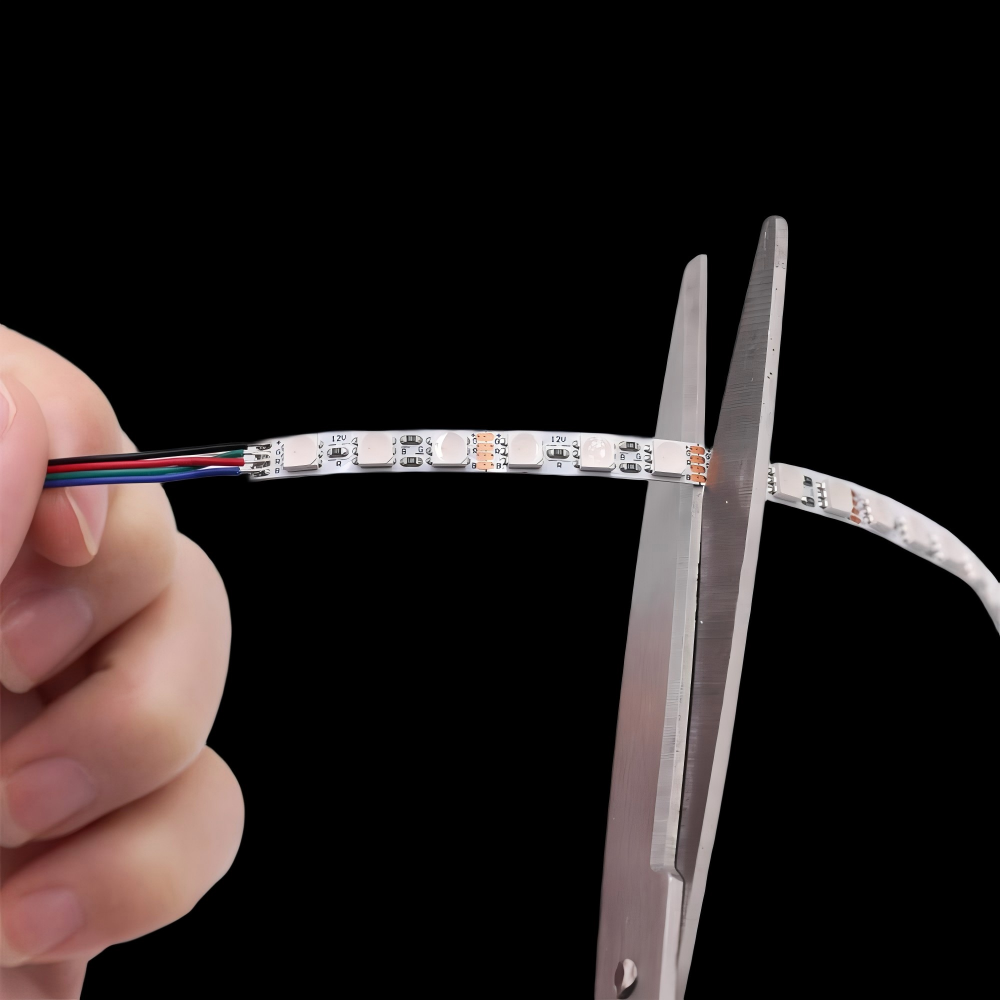
A narrow PCB has less area for:
- Copper tracks
- Heat spreading
- Adhesive contact
- Transfer to the mounting surface
Ultra-narrow strips can work reliably when wattage and mounting are engineered together, but they should not automatically be driven at the same power density as wider products.
For compact furniture or product integration, Xmart’s ultra-narrow LED strip range can be matched with suitable profiles and project-specific wattage.
4. Insufficient copper cross-section
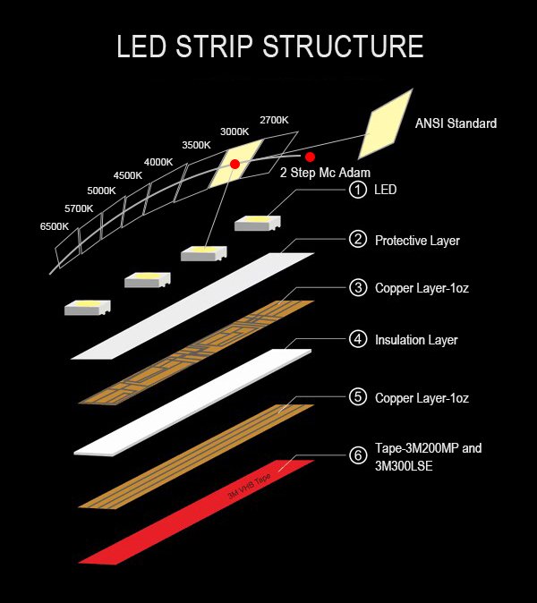
PCB resistance depends on both copper thickness and track geometry.
Higher resistance creates:
- Additional electrical loss
- Greater temperature rise
- More voltage drop
- Possible brightness variation
“2oz copper” is useful information, but it does not describe track width, bottlenecks, solder pads or the current carried by each channel.
5. Overvoltage
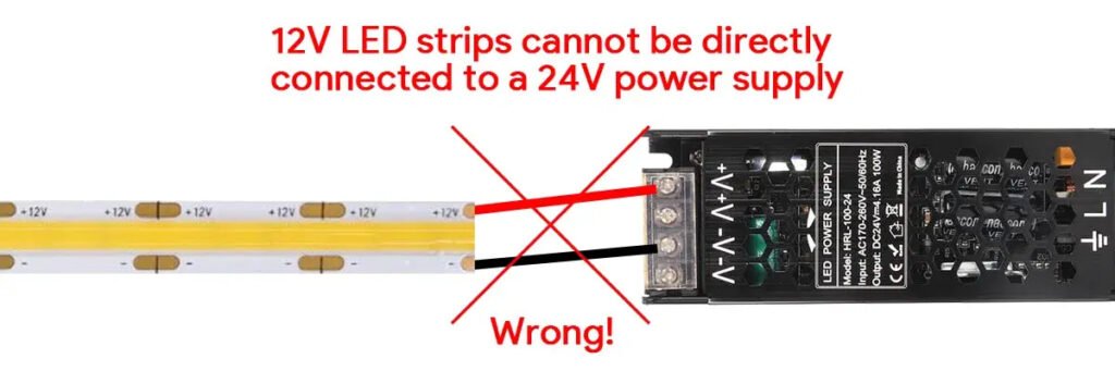
Connecting a 12V strip to 24V is an obvious fault, but smaller overvoltage can also increase current and heat.
Verify voltage at the strip input—not only at the driver label.
Some installers increase driver output voltage to compensate for voltage drop at the far end. This can overdrive the first strip sections even when the final section appears brighter.
Solve voltage drop with correct cable size, feed points or strip architecture rather than excessive input voltage.
6. Operating while coiled
A full LED strip reel should not normally be operated at maximum output while tightly coiled unless the manufacturer explicitly permits it.
When coiled:
- Each layer heats the next
- Airflow is restricted
- Inner sections cannot release heat
- Waterproof material traps additional heat
- The reel core stores thermal energy
Always unroll the strip and prevent overlap before full-power testing.
7. Enclosed installation
A profile can transfer heat away from the PCB, but the heat must eventually escape from the profile.
A large aluminum extrusion inside a sealed, insulated cavity can continue becoming hotter because the surrounding assembly cannot release the energy.
Thermal performance depends on:
- Profile mass
- Exposed surface area
- Air movement
- Contact with the building structure
- Cavity dimensions
- Insulation
- Diffuser
- Installation orientation
8. Waterproof encapsulation
Waterproofing protects against moisture but can increase thermal resistance.
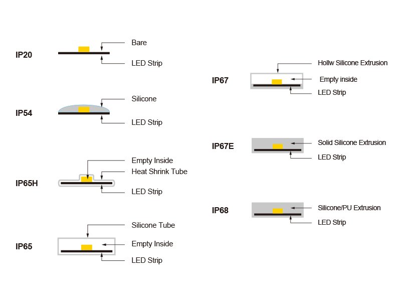
Silicone coating, tubing, solid extrusion and potting materials do not have identical thermal properties. Air gaps inside sleeves can further reduce heat transfer.
Do not assume the IP20, IP65, IP67 and IP68 versions of one strip have the same maximum wattage or operating temperature.
9. Multiple strips installed side by side
Two 15W/m strips mounted in one narrow profile create a different thermal load from one 15W/m strip.
The profile must dissipate the combined watts per meter.
Closely spaced strips can also heat one another, particularly under a shared diffuser.
10. High-resistance connections
A loose connector can become much hotter than the strip around it.
Local heat follows:
Connection heat = current² × contact resistance
Even a small resistance becomes important at high current.
Warning signs include:
- One connector hotter than identical connectors
- Discolored plastic
- Brown copper pads
- Softened insulation
- Intermittent operation
- Burning odor
- Heat concentrated at one solder joint
A localized hot spot is usually more concerning than a uniformly warm profile.
Does Every LED Strip Need an Aluminum Profile?
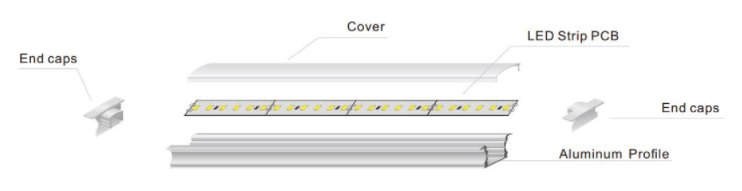
No—but many medium- and high-power installations benefit from one.
An aluminum profile can provide:
- Heat spreading
- Larger heat-transfer area
- Mechanical support
- More reliable adhesion
- Protection against physical damage
- Cleaner optical diffusion
However, an aluminum profile is not a universal cure.
A profile may still perform poorly when:
- It is too small for the thermal load
- The strip has poor contact with the aluminum
- Adhesive creates air gaps
- The profile is inside a sealed cavity
- Several strips share one narrow channel
- Ambient temperature is high
- The diffuser restricts heat release
- The profile is surrounded by insulation
Select the profile by total watts per meter, installation space and measured temperature—not only by PCB width.
Xmart’s LED aluminum profile range includes furniture and architectural profiles with different dimensions and aluminum mass. A project profile should be tested together with the actual strip and diffuser.
Adhesive Tape Is Not a Heat Sink
The rear adhesive attaches the strip to a surface. It does not replace a proper thermal path.
Poor adhesion creates air gaps that reduce heat transfer. As the strip becomes hotter, the adhesive may soften, creep or detach, creating an accelerating failure cycle:
- Strip temperature rises.
- Adhesive loses strength.
- Parts of the strip lift from the profile.
- Thermal contact becomes worse.
- The lifted section becomes hotter.
- The strip curls, sags or overlaps.
For commercial installations, surface preparation and mechanical retention may be as important as adhesive brand.
Are COB LED Strips Hotter Than SMD Strips?
Not inherently.
COB and SMD describe different package and assembly structures. Operating temperature still depends mainly on:
- Electrical watts per meter
- Luminous efficacy
- PCB width and copper
- Drive current
- Encapsulation
- Mounting method
A 16W/m COB strip can run hotter than an 8W/m SMD strip. A high-efficacy 10W/m COB strip can run cooler than a lower-efficacy 15W/m SMD strip while producing similar light.
The dotless appearance of COB does not prove better thermal performance.
Why the Start of a Long Strip May Be Hotter
In a conventional constant-voltage strip, the first PCB sections carry the current required by all downstream sections.
As voltage drops along the run:
- The start may carry greater current
- The far end may draw less power
- The far end may be cooler because it is producing less light
A cooler far end is therefore not always good news. It may indicate voltage drop and reduced output.
Measure voltage, current, temperature and light distribution together.
How Heat Affects LED Strip Lifespan
Excess temperature can accelerate:
- LED lumen depreciation
- Color shift
- Phosphor degradation
- Solder-joint fatigue
- PCB delamination
- Resistor and IC stress
- Silicone yellowing
- Adhesive failure
- Connector oxidation
- Driver-component aging
DOE lifetime guidance emphasizes that thermal management, drive current and junction temperature are critical to LED-system reliability. It also notes that the lifetime of the complete lighting product depends on much more than the LED package alone. See the DOE LED Luminaire Lifetime Recommendations.
Does every 10°C rise cut LED life in half?
Not as a universal rule.
The “life halves for every 10°C” statement is a simplified acceleration heuristic used for certain components and failure mechanisms. It cannot accurately predict the lifetime of every LED strip.
Different materials and components follow different aging models. A defensible lifetime estimate requires:
- Exact operating temperature
- LED LM-80 data
- Drive current
- Relevant thermal resistance
- TM-21 projection where applicable
- Driver lifetime data
- Material ratings
- Complete-system reliability assumptions
Use the 10°C rule as a reminder that heat matters—not as a warranty calculation.
LM-80 Does Not Prove a 50,000-Hour LED Strip Life
LM-80 measures lumen maintenance and color behavior of LED packages, arrays or modules under defined operating conditions.
It does not automatically test:
- Flexible PCB
- Solder joints
- Resistors
- Current-regulation ICs
- Connectors
- Adhesive
- Waterproof silicone
- Driver
- Final installation
A supplier should not convert an LED package LM-80 report directly into an unconditional 50,000-hour claim for every finished LED strip configuration.
For a serious project, ask for:
- Exact LED model
- LM-80 report
- Applicable test temperature and current
- TM-21 projection
- Measured strip Tc or Ts
- Complete strip thermal test
- Driver lifetime information
- Warranty conditions
Standard LED Strips Should Not Be Used in Saunas
A standard indoor strip is not suitable merely because its measured PCB temperature stayed below 60°C in a room-temperature test.
Saunas combine:
- High ambient temperature
- Humidity or steam
- Thermal cycling
- Wood construction
- Restricted driver locations
- Material-outgassing concerns
- Difficult maintenance access
Use a product specifically designed and tested for the required zone and temperature.
Xmart’s sauna LED strip range includes model-specific high-temperature configurations and test-report options. The strip, cable, seals and mounting method must be matched to the actual sauna zone, and the driver and controller should be positioned outside the high-temperature area where required.
An IP rating alone does not prove high-temperature suitability.
When Should You Switch Off the LED Strip?
Disconnect power and investigate if you find:
- Burning or chemical odor
- Brown or black marks
- Softened connectors
- Deformed diffuser or plastic
- Bubbling or delaminated PCB
- Melted adhesive
- Smoke
- Repeated driver thermal shutdown
- One point much hotter than the surrounding strip
- Temperature continuing to rise without stabilizing
- Input voltage above the strip rating
- A powered strip that is coiled or overlapping
For fire and electrical risks, see Can LED Strip Lights Cause a Fire?.
Step-by-Step LED Strip Overheating Troubleshooting
Step 1: Switch off and inspect
Look for:
- Overlap
- Sharp folds
- Damaged PCB
- Loose connectors
- Discoloration
- Poor adhesive contact
- Blocked profile ventilation
Step 2: Confirm voltage and driver type
Verify:
- Strip rated voltage
- Driver output voltage
- Constant-voltage or constant-current requirement
- Polarity
- Dimming compatibility
Step 3: Measure actual power
Calculate:
Actual power = measured voltage × measured current
Compare the result with the expected load for the installed length.
Unexpectedly high power may indicate overvoltage, incorrect control operation or the wrong product.
Unexpectedly low power may indicate voltage drop, dimming, poor connections or a product that does not perform at its declared rating.
Step 4: Test the strip unrolled
Never compare a coiled test with a mounted installation.
Unroll the strip, prevent overlap and install it on the intended profile or test surface.
Step 5: Find the hottest location
Use a thermal camera first, then confirm critical points with a contact sensor where practical.
Step 6: Improve the thermal path
Possible solutions include:
- Larger aluminum profile
- Better strip-to-profile contact
- Lower watts per meter
- Higher-efficacy strip
- More ventilation
- Fewer strips per profile
- Lower ambient temperature
- Moving the driver outside the enclosure
- Selecting a product qualified for the environment
Step 7: Repeat the complete test
Retest at:
- Maximum allowed output
- Worst credible color scene
- Highest expected ambient temperature
- Final diffuser and enclosure configuration
Thermal Acceptance Test for LED Strip Samples
For commercial or OEM projects, use a repeatable test method.
Test conditions
Record:
- Product model and production batch
- Voltage
- Watts per meter
- Total length
- Feed method
- Profile model
- Diffuser type
- Mounting orientation
- Ambient temperature
- IP construction
- Dimming level
- Test duration
Measurement points
Measure:
- Strip input
- 25% of the run
- Center of the run
- 75% of the run
- Far end
- Every connector type
- Profile surface
- Driver Tc point
Acceptance criteria
The project specification should define:
- Maximum permitted PCB or Tc temperature
- Maximum connector temperature
- Maximum profile temperature for accessible locations
- Maximum temperature difference between repeated points
- Stabilization method
- Highest operating ambient
- Required electrical and photometric performance
Do not create the acceptance limit after the sample has already been tested.
What LED Strip Buyers Should Request
Before placing a large order, request:
- Maximum operating ambient temperature
- Maximum PCB, Tc or reference-point temperature
- Temperature measurement location
- Watts per meter tolerance
- LED manufacturer and package model
- LED LM-80 data
- Recommended profile
- Thermal test with profile and diffuser
- IP-version thermal comparison
- PCB width and copper construction
- Driver derating curve
- Connector current rating
- Adhesive temperature rating
- Warranty temperature conditions
- High-temperature or sauna reports where relevant
Xmart can evaluate strip wattage, PCB width, efficacy, waterproof structure and aluminum profile as one thermal system. For a project-specific recommendation, submit the profile drawing, ambient temperature and required lumens through the Xmart project quotation form.
Frequently Asked Questions
What temperature should an LED strip normally reach?
Many properly installed indoor strips operate with a PCB or profile surface temperature somewhere between approximately 35°C and 60°C. The correct limit must come from the exact product specification and installation test.
Is 50°C too hot for an LED strip?
Not necessarily. It may be acceptable for some products, but the measurement location, ambient temperature and component ratings must be known. A 50°C PCB and a 50°C connector do not necessarily represent the same risk.
Is 60°C too hot for an LED strip?
A 60°C surface temperature is elevated and should be validated against the manufacturer’s maximum Tc, PCB and material ratings. It should not automatically be accepted or rejected without product data.
Is it normal for an LED strip to be too hot to touch?
An LED strip or aluminum profile can feel too hot for comfortable prolonged contact while still remaining within certain component limits. Touch is not a reliable safety or lifetime test. Measure the temperature.
Can LED strips overheat on wood?
Yes. Wood and MDF do not spread heat as effectively as aluminum. Whether installation is acceptable depends on strip power, temperature testing, product instructions and applicable requirements.
Do low-voltage LED strips produce heat?
Yes. Low voltage reduces shock risk in appropriate systems but does not eliminate heat. A 12V strip can carry high current, creating substantial PCB, cable and connector losses.
Does 24V run cooler than 12V?
At the same total power and conductor design, 24V carries half the current and can reduce distribution losses. However, two different 12V and 24V strip designs may have different LED drive currents and thermal performance.
Does dimming reduce LED strip temperature?
Usually, reducing average power lowers temperature. However, the installation should normally be validated at its maximum permitted output and worst credible operating scene.
Which RGBW setting produces the most heat?
The worst case depends on controller programming and strip architecture. Full combined output may create the highest load, but some controllers limit the total current. Test the maximum permitted channel combination rather than assuming.
Can a waterproof LED strip overheat?
Yes. Waterproof material can increase thermal resistance and trap heat. Use the thermal data for the exact IP construction.
Do aluminum channels make LED strips cooler?
Usually, when correctly sized and installed, aluminum profiles spread heat and reduce PCB temperature. The actual improvement depends on profile mass, contact, airflow, enclosure and ambient temperature.
Can aluminum profiles prevent every overheating problem?
No. They cannot correct overvoltage, excessive wattage, a hot connector, poor ventilation or an unsuitable high-temperature environment.
Why is only one part of my strip hot?
A localized hot area may indicate a loose connector, poor solder joint, damaged PCB, component fault, overlap or poor thermal contact. Switch off and investigate it.
Can I test an LED strip while it is still on the reel?
Do not operate a tightly coiled reel at full output unless the manufacturer explicitly permits it. Unroll it before testing.
Does a cooler LED strip always last longer?
Lower operating temperature generally reduces thermal stress, but lifetime also depends on drive current, moisture, materials, electrical protection, manufacturing quality and installation.
Final Recommendation
Do not judge LED strip temperature by touch or by one universal number.
For many indoor projects, a stabilized PCB or profile temperature between approximately 35°C and 60°C may be expected. Once temperatures approach or exceed 60–70°C, the product and installation deserve closer engineering validation. Temperatures above 70–80°C should not be accepted for a standard strip without clear manufacturer data and system-level testing.
The correct process is:
- Identify the exact product temperature limit.
- Install the strip in its final profile and enclosure.
- Operate it at the worst permitted load.
- Wait for thermal stabilization.
- Measure the PCB, connectors, profile and driver.
- Compare the results with documented component and system limits.
- Repeat the test at the highest expected ambient temperature.