LED strip lights flicker when the electrical current reaching the LEDs is unstable.
In most installations, the LED strip is not the first component to blame. Flicker is more commonly caused by an overloaded power supply, an incompatible dimmer, unstable PWM control, voltage drop, loose connections, undersized wiring or a driver entering protection mode.
The fastest way to isolate the problem is:
Run the strip at full brightness → bypass the dimmer → disconnect part of the load → measure voltage under load → inspect connections → check temperature.
This guide explains 12 common causes of LED strip flicker, how to recognize each one and what to test before replacing any components.
Quick LED Strip Flicker Diagnosis
| What you see | Most likely cause | First test |
|---|---|---|
| The entire strip flashes on and off every few seconds | Power-supply overload or protection mode | Disconnect half of the strip |
| The strip flickers only when dimmed | Dimmer, driver or controller incompatibility | Bypass the dimming device |
| Flicker begins below 10–20% brightness | Minimum dimming limit or unstable PWM | Increase the minimum brightness |
| Only the far end flickers or changes color | Voltage drop | Measure voltage at both ends |
| Flicker changes when a connector is touched | Loose or high-resistance connection | Remake the connection |
| Flicker begins after several minutes | Thermal protection | Check driver and controller temperature |
| RGB flicker appears only on white or mixed colors | Controller or power-supply overload | Test one channel at a time |
| Only one cut section flickers | Local strip or solder-joint failure | Bypass the affected section |
| Several lights flicker when machinery starts | AC input disturbance | Test on a separate circuit |
| The strip is stable to the eye but shows camera bands | PWM and camera-shutter interaction | Change the shutter speed or controller |
| The strip flickers after it is switched off | Dimmer leakage or smart-switch standby current | Bypass the electronic switch |
Flicker, Flashing and Camera Banding Are Different Problems
Before replacing anything, identify what “flicker” means in your installation.
Slow flashing or power cycling
If the whole strip switches completely on and off every few seconds, the power supply may be entering overload, short-circuit or thermal protection.
The typical cycle is:
Power on → fault detected → power off → automatic restart → fault detected again
This is usually an electrical protection problem, not a subtle optical flicker problem.
Visible flicker
Visible flicker is a repeated brightness change that can be seen while looking directly at the light.
It is commonly associated with unstable power, low-frequency modulation or dimming incompatibility.
Stroboscopic effect
The strip may look stable while everything is stationary, but moving hands, fans, tools or machine parts appear to jump or separate into multiple positions.
Phantom array
When the viewer moves their eyes quickly, a modulated light source may appear as repeated dots or broken images.
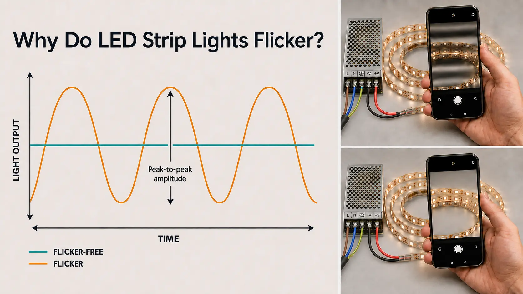
Camera banding
A phone or camera may show dark bands even when the light looks stable to the human eye.
Camera banding depends on:
- PWM frequency
- Modulation depth
- Light-output waveform
- Frame rate
- Shutter speed
- Rolling-shutter scanning
- Exposure settings
- Dimming level
A smartphone is useful for comparison, but it cannot certify that an LED system is flicker-free.
The U.S. Department of Energy uses the broader term temporal light modulation, or TLM, because frequency alone cannot describe the complete effect. Waveform, duty cycle and modulation depth also matter. Read the DOE overview of temporal light modulation.
The Four-Layer Flicker Diagnosis Model
A professional diagnosis should follow the electrical path through the installation.
Layer 1: AC input and power supply
Check:
- AC voltage quality
- Power-supply capacity
- Output ripple
- Voltage regulation
- Protection modes
- Thermal derating
Layer 2: Dimming and control
Check:
- TRIAC or phase-cut dimming
- 0–10V
- DALI
- PWM
- DMX512
- Smart controllers
- RGB/RGBW amplifiers
- Minimum dimming level
Layer 3: Low-voltage power distribution
Check:
- Wire gauge
- Cable length
- Connectors
- Terminal blocks
- Power injection
- PCB voltage drop
- Branch loading
Layer 4: LED strip and environment
Check:
- Damaged sections
- Poor solder joints
- Failed components
- Moisture
- Corrosion
- Excessive heat
- Incorrect cutting or bending
Testing these layers in order helps prevent unnecessary LED strip replacement.
Before Troubleshooting
Confirm the rated voltage
A 12V strip requires a regulated 12V DC supply. A 24V strip requires a 24V DC supply.
Check the voltage on:
- The strip PCB
- The reel label
- The power supply
- The controller
- The product specification
Unroll the strip
Do not operate a high-power strip for an extended period while it is tightly coiled. Trapped heat can damage the LEDs and PCB or trigger driver protection.
Switch off power before touching connections
Inspect connectors and terminals only after isolating the system.
Mains-voltage wiring should be tested by a qualified electrician.
Measure under load
A power supply may show the correct output voltage when disconnected and collapse only after the LED strip is operating.
A 90-Second Isolation Test
Test 1: Set the strip to full brightness
If the flicker disappears, investigate the dimming or control system.
If the flicker remains, investigate the power supply, wiring and strip.
Test 2: Bypass the dimmer or controller
Where the system design permits, operate the strip from a known-good constant-voltage supply.
If the strip becomes stable, the fault is probably in the control chain.
Test 3: Disconnect half of the strip
If the remaining strip becomes stable, investigate:
- Power-supply capacity
- Controller capacity
- Voltage drop
- Connector current
- Thermal derating
Test 4: Measure the beginning and far end
Measure both points while the strip is operating at its highest expected load.
If the input voltage is stable but the far-end voltage is low, the problem is in the low-voltage distribution system.
12 Causes of LED Strip Flicker
1. The Power Supply Is Overloaded
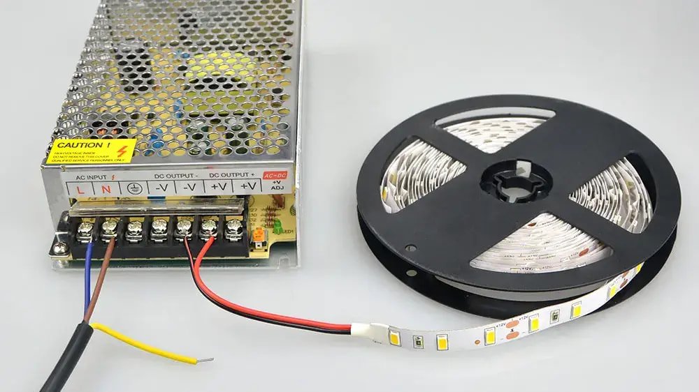
An overloaded power supply commonly causes slow, rhythmic flashing.
When the connected strip demands more power than the supply can deliver, the supply may enter protection mode. Some power supplies shut down completely. Others reduce output current or repeatedly attempt to restart.
Calculate the nominal load
Total strip power = wattage per meter × total length
Example:
- Strip power: 14.4W/m
- Total length: 10m
- Nominal load: 144W
- Current at 24V: 144W ÷ 24V = 6A
A 150W power supply provides only 6W of nominal spare capacity. That may be insufficient after temperature derating, tolerances and controller losses are considered.
Approximately 20% headroom is a common planning starting point, but it is not a universal requirement. Always check the power-supply manufacturer’s loading and temperature curves.
MEAN WELL explains that power supplies may use shutdown, constant-current or pulsing hiccup protection when overloaded. See MEAN WELL’s explanation of protection modes.
How to fix it
- Use a correctly sized power supply.
- Divide the installation into separate powered zones.
- Reduce the connected strip length.
- Check controller capacity as well as driver capacity.
- Derate drivers installed in hot or enclosed spaces.
- Confirm whether startup inrush affects the system.
A larger constant-voltage supply does not push excessive wattage into a correctly designed strip. However, its output voltage must match the strip.
2. The Power Supply Has Excessive Ripple
A power supply can have sufficient rated wattage and still create flicker.
LEDs respond very quickly to current changes. If the driver output contains excessive ripple, unstable regulation or repeated voltage dips, the light output can follow those changes.
Possible causes include:
- Inadequate filtering
- Aging capacitors
- Poor AC input
- Low-cost driver topology
- Operation close to maximum load
- A defective power supply
Typical symptoms
- The entire strip flickers at full brightness.
- The problem becomes worse as load increases.
- A known-good driver solves the problem.
- Camera bands appear without a dimmer.
- Output voltage changes under a steady load.
A standard multimeter may average rapid variations and display an apparently normal voltage.
Better diagnostic tools include:
- An oscilloscope
- A photodiode
- A calibrated flicker meter
- A known-good comparison driver
MEAN WELL notes that AC fluctuations and excessive output ripple can cause visible LED brightness variation. Read the technical explanation.
3. The Output Voltage or Driver Type Is Wrong
Most conventional LED strips use a constant-voltage power supply.
Typical combinations include:
- 12V strip with a 12V constant-voltage supply
- 24V strip with a 24V constant-voltage supply
- 36V strip with a 36V constant-voltage supply
- 48V strip with a 48V constant-voltage supply
Supplying 24V to a standard 12V strip can overdrive the LEDs and resistors, causing excessive heat and rapid failure.
Supplying 12V to a 24V strip normally creates very low or unstable output.
Do not connect a conventional constant-voltage strip to a constant-current driver unless the system is specifically designed for that combination.
Some long-run LED strips contain current-regulating ICs on the PCB but still require a constant-voltage supply. “Constant-current strip” does not automatically mean “use a constant-current driver.”
For additional product-selection guidance, see Xmart’s LED strip selection guide.
4. The AC Input Is Unstable
The strip operates on low-voltage DC, but its power supply is connected to the AC electrical system.
Disturbances can come from:
- Motors
- Compressors
- Elevators
- Welding equipment
- Generators
- Phase-cut loads
- Loose neutral connections
- Significant voltage fluctuations
- Poor circuit separation
Typical symptoms
- Several lights flicker simultaneously.
- Flicker starts when a motor or air conditioner switches on.
- The system works in the factory but not on site.
- The problem follows a building-equipment cycle.
- The strip works correctly on a bench supply.
How to fix it
- Test the driver on a separate circuit.
- Record the AC voltage during the event.
- Check whether other lighting is affected.
- Use a driver with suitable input immunity.
- Ask a qualified electrician to inspect the circuit.
A larger DC power supply cannot correct a faulty AC installation.
5. The Dimmer, Driver and Controller Are Incompatible
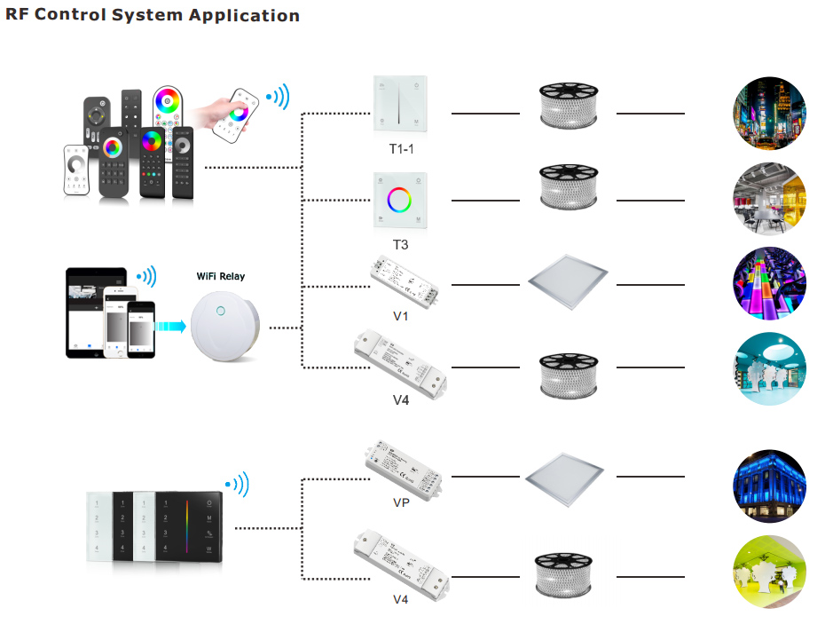
“Dimmable” does not describe one universal system.
LED strip projects may use:
- TRIAC
- 0–10V
- DALI
- PWM
- DMX512
- KNX
- Casambi
- Zigbee
- Bluetooth
- Wi-Fi
- Matter-compatible controllers
These are different control architectures.
For example, a TRIAC wall dimmer requires a compatible phase-dimmable power supply. A standard non-dimmable constant-voltage supply should not be installed behind a phase-cut dimmer unless the manufacturer approves the combination.
A DALI command does not directly power the strip. The DALI driver or controller receives the command and produces the electrical output used by the strip.
How to confirm it
Test in three stages:
- Power supply and strip
- Power supply, controller and strip
- Complete dimming system
If the first combination is stable but the complete system flickers, the strip is probably not defective.
How to fix it
- Match the dimmer to the driver input.
- Confirm the driver output type.
- Use a tested compatibility list.
- Check minimum and maximum load.
- Avoid mixing control protocols without the correct interface.
- Test the exact driver, controller and strip combination.
Xmart’s smart-home LED strip systems show how the driver, controller and strip work together as one system.
6. The System Is Unstable at Low Brightness
A strip may dim smoothly from 100% to 20%, then flicker, jump or turn off below that point.
Possible causes include:
- Minimum holding current in a phase-cut driver
- Very short PWM pulses
- Poor low-duty-cycle resolution
- Driver minimum-load requirements
- Control-signal noise
- An incorrectly adjusted dimmer trim
- A driver changing dimming methods
Typical symptoms
- Flicker begins at the same brightness level.
- The strip suddenly drops out before reaching zero.
- The strip “pops on” when brightness is increased.
- Changing the connected load changes the problem.
- The system works correctly at full output.
How to fix it
- Adjust the dimmer’s minimum-level trim.
- Use a driver with a lower tested dimming floor.
- Meet the driver’s minimum-load requirement.
- Avoid mixing different driver models.
- Test at 100%, 50%, 20%, 10% and minimum output.
A claim of “1% dimming” should explain whether it means control-signal level, measured light output or perceived brightness.
7. The PWM Frequency or Modulation Depth Is Unsuitable
PWM controls brightness by switching the LEDs rapidly between on and off.
PWM is not automatically poor-quality dimming. Its performance depends on:
- Switching frequency
- Modulation depth
- Duty cycle
- Waveform stability
- Controller resolution
- Minimum brightness
- Application
- Camera settings
Why frequency alone is not enough
A controller operating at 2kHz may look stable in a hotel cove but create bands in a television studio.
A higher-frequency system can still perform poorly when:
- Light output falls completely to zero during every cycle.
- Pulse timing is unstable.
- Duty cycle becomes irregular at low brightness.
- The power supply cannot respond to load changes.
- Multiple controllers are unsynchronized.
DOE research indicates that temporal light effects can remain detectable at frequencies above those normally associated with visible flicker.
Therefore, “above 2kHz” should not be treated as a universal flicker-free guarantee.
How to improve performance
- Select PWM frequency for the actual application.
- Use camera-compatible controllers for filming environments.
- Consider current-reduction or hybrid dimming.
- Request waveform and modulation data.
- Test at the lowest required brightness.
- Test with the actual camera.
8. The Controller or Amplifier Is Overloaded
The power supply may be large enough while the controller remains undersized.
Controllers normally have:
- Maximum total current
- Maximum current per channel
- Operating-voltage range
- Thermal limits
- PWM frequency
- Maximum output power
For RGBW and RGBCCT systems, the highest load may occur when several channels operate simultaneously.
Typical symptoms
- Single colors work, but full white flickers.
- Flicker appears during dynamic scenes.
- One channel behaves differently.
- The controller becomes hot.
- Disconnecting part of the load solves the problem.
How to fix it
- Calculate per-channel and total current.
- Divide the strip into properly powered zones.
- Use correctly rated signal amplifiers.
- Derate controllers installed in enclosures.
- Provide adequate ventilation.
- Do not route excessive strip current through the controller.
For multichannel system options, see Xmart’s RGB, RGBW and RGBCCT LED strips.
9. Voltage Drop Is Starving the Far End
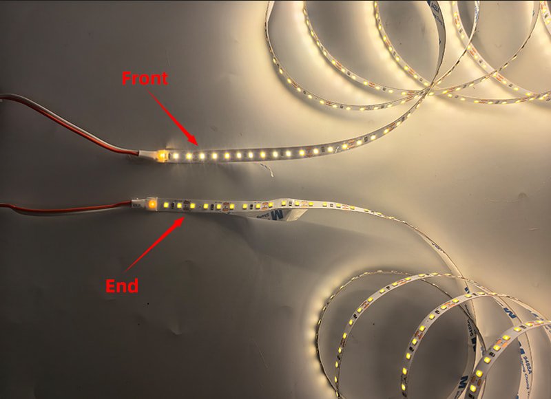
Voltage drop normally begins as brightness loss but can develop into flicker, color instability or controller resets.
It becomes more likely when:
- Strip runs are long.
- Wattage per meter is high.
- Supply voltage is low.
- Feed cables are long.
- PCB copper traces are narrow.
- Multiple color channels turn on together.
Calculate voltage-drop percentage
Voltage drop percentage = (input voltage − end voltage) ÷ input voltage × 100
Example:
- Strip input: 24.0V
- Far end: 21.8V
- Voltage loss: 2.2V
- Voltage drop: 2.2 ÷ 24 × 100 = 9.17%
A drop above 9% is likely to create visible brightness or color differences on many 24V strips.
The acceptable limit depends on strip design and visual requirements, so one percentage should not be treated as universal.
Measure at five points
Measure under maximum expected load at:
- Power-supply output
- Controller input
- Controller output
- Strip beginning
- Strip far end
This separates cable loss, controller loss and PCB loss.
How to fix it
- Add power injection.
- Feed both ends.
- Use a center-feed layout.
- Increase conductor size.
- Shorten individual branches.
- Move from 12V to 24V.
- Use 36V or 48V where appropriate.
- Select thicker-copper or current-regulated strips.
For extended installations, review Xmart’s 36V and 48V long-run LED strip systems.
Why higher voltage helps
For the same 144W load:
| System voltage | Approximate current |
| 12V | 12A |
| 24V | 6A |
| 48V | 3A |
Higher voltage reduces current and can reduce cable and PCB losses.
It does not eliminate power-supply ripple, dimmer incompatibility or PWM-related flicker.
10. A Connection or Cable Has Excessive Resistance
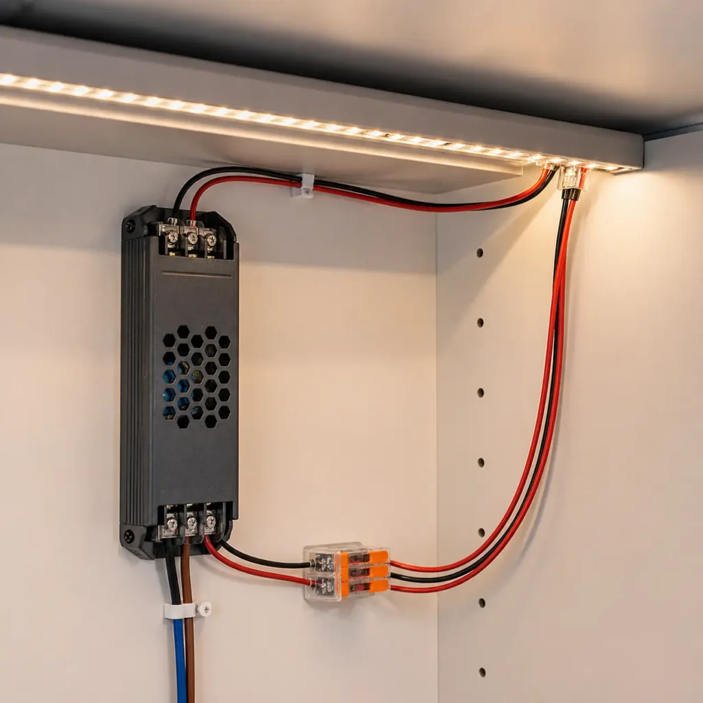
Loose connectors, undersized wires and poor solder joints add resistance to the power path.
A damaged connection may become intermittent as it heats up or moves.
Common causes
- Incorrect connector width
- Misaligned copper pads
- Insufficient contact pressure
- Waterproof coating left on the pads
- Loose terminal screws
- Partially captured wire strands
- Poor solder wetting
- Undersized conductors
- Overloaded connectors
- Corrosion
How to confirm it
- Measure voltage before and after the connection.
- Check the joint at full load.
- Compare its temperature with nearby joints.
- Look for darkened plastic or oxidized copper.
- Check whether movement changes the symptom.
A thermal camera can reveal a high-resistance connection before the connector visibly melts.
How to fix it
- Remake the connection on clean copper.
- Use the correct connector size and pad layout.
- Confirm current ratings.
- Increase conductor size.
- Add strain relief.
- Replace heat-damaged terminals.
- Use properly soldered and sealed joints in demanding environments.
11. The Driver or Controller Is Overheating
Thermal protection often looks like electrical overload.
The installation starts normally, operates for several minutes, then flickers or shuts down. After cooling, it works again.
Common causes
- Driver installed in a sealed ceiling
- Controller operating near maximum current
- Waterproof box with no thermal path
- High ambient temperature
- Driver covered by insulation
- Insufficient ventilation
- Strip powered while still coiled
How to confirm it
Record the time from cold startup to the first fault.
A thermal problem is likely when:
- The interval is repeatable.
- Flicker begins sooner in warmer conditions.
- Reducing the load delays the fault.
- Cooling restores normal operation.
How to fix it
- Reduce the load.
- Improve airflow.
- Follow spacing requirements.
- Move the driver away from heat.
- Apply temperature derating.
- Use a higher-temperature-rated driver.
- Divide the load across multiple devices.
An aluminum profile may cool the strip, but it cannot cool an overloaded driver inside a sealed enclosure.
12. A Strip Segment Is Damaged
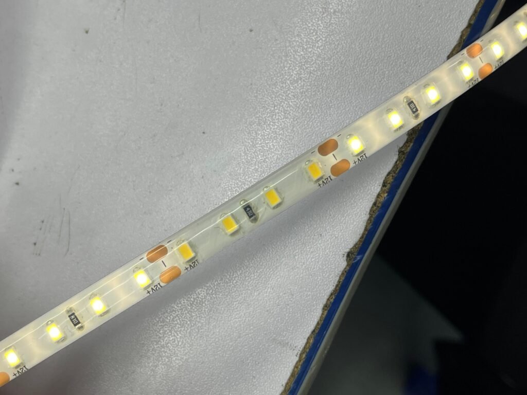
Replace the strip only after testing the upstream system.
Local failures may include:
- Cracked PCB traces
- Failed resistors
- Damaged current-regulating ICs
- Weak LED-package connections
- Poor solder joints
- Incorrect cutting
- Excessive bending
- Electrostatic damage
- Moisture ingress
- Corrosion
- Overvoltage damage
Symptom patterns
| Symptom | Likely problem |
| One cut section flickers | Local PCB, resistor or LED failure |
| One color channel fails along the entire run | Controller or channel wiring |
| Flicker begins after a sharp bend | Cracked PCB trace |
| Flicker begins after water exposure | Moisture or corrosion |
| Random addressable pixels flash | Data, grounding or signal integrity |
| The same section fails with another supply | Strip-level defect |
How to fix it
- Remove and replace the damaged section at an approved cut point.
- Inspect the adjacent copper pads.
- Correct data wiring on addressable strips.
- Remake wet-area joints using the correct sealing process.
- Do not seal visible moisture inside a repaired connection.
For other problems such as dead sections, color faults or overheating, use Xmart’s complete LED strip troubleshooting guide.
Why Does an LED Strip Flicker After It Is Switched Off?
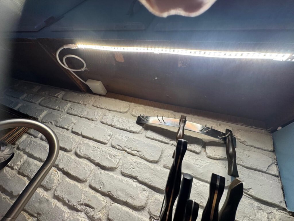
A strip that flashes or glows faintly after being switched off may be receiving a small leakage current.
Possible sources include:
- Electronic smart switches
- Illuminated wall switches
- Phase-cut dimmers
- Two-wire smart controls
- Capacitive coupling in long cables
- Incorrect switching of the neutral instead of the live conductor
- Driver input circuits storing or periodically releasing energy
How to confirm it
Temporarily bypass the electronic switch using a safe, approved test method.
If the problem disappears with a mechanical isolation switch, investigate standby current or control compatibility.
Do not add a random resistor across the mains input. Any bypass device must be approved for the driver, dimmer and local electrical regulations.
Step-by-Step Troubleshooting Process
Step 1: Record the system
Write down:
- Strip voltage
- Wattage per meter
- Total length
- Power-supply model
- Controller model
- Dimming protocol
- Brightness level
- Color setting
- Ambient temperature
- Time before flicker begins
Step 2: Classify the location
Determine whether flicker affects:
- The whole installation
- One power-supply zone
- One controller output
- One color channel
- The far end
- One cut segment
- Only the camera
Step 3: Test at full brightness
If the flicker disappears, investigate the dimming chain.
If it remains, investigate power, wiring and connections.
Step 4: Bypass the control stage
Test with a known-good power supply and a short strip sample.
Step 5: Reduce the load
Disconnect part of the strip.
If the problem disappears, check every current-carrying component—not only the power supply.
Step 6: Measure voltage under load
Use the highest-power operating condition, such as full white on an RGBW strip.
Step 7: Inspect temperature and connections
Look for loose terminals, discoloration, corrosion and abnormal heat.
Step 8: Substitute one component at a time
Change only one item:
- Power supply
- Controller
- Dimmer
- Cable
- Connector
- Strip sample
Changing several components at once may remove the symptom without identifying the root cause.
How Should LED Strip Flicker Be Measured?
Smartphone camera
Useful for:
- Quick comparisons
- Detecting severe camera banding
- Comparing dimming levels
Not suitable for:
- Compliance testing
- Measuring PstLM or SVM
- Predicting all human responses
- Comparing unrelated camera models
Multimeter
Useful for:
- Checking rated voltage
- Measuring voltage drop
- Finding major instability
A standard meter may average rapid changes.
Oscilloscope
Useful for measuring:
- PWM frequency
- Duty cycle
- Output ripple
- Voltage dips
- Restart cycles
- Controller instability
Photodiode or flicker meter
A photodiode measures actual optical output over time.
This is more useful than measuring voltage alone because stable average voltage does not always mean stable light output.
Which Flicker Metrics Matter?
| Metric | What it describes | Main limitation |
| Frequency | Repetition rate | Does not describe modulation depth |
| Percent flicker | Maximum-to-minimum variation | Does not fully account for frequency |
| Flicker index | Waveform area and shape | Incomplete on its own |
| PstLM | Short-term visible flicker response | Does not predict camera compatibility |
| SVM | Stroboscopic-effect visibility | Does not describe every temporal effect |
| Modulation depth | Size of light-output variation | Requires frequency and waveform context |
| Waveform | Light output over time | Requires application-specific interpretation |
For light sources within the scope of the EU ecodesign regulation, full-load limits generally include:
- PstLM ≤ 1.0
- SVM ≤ 0.4
The SVM requirement has generally applied since September 2024, subject to the regulation’s scope and exceptions. See EU Regulation 2019/2020.
Passing at full output does not prove acceptable performance at 50%, 20%, 10% or minimum brightness.
A Better Low-Flicker Project Specification
Instead of specifying only “flicker-free LED strip,” use a complete-system requirement:
The LED strip, power supply and control device shall be tested as one operating system. The supplier shall identify the dimming method, output waveform, PWM frequency where applicable, minimum stable dimming level, PstLM and SVM values, connected load and test conditions. Testing shall be completed at 100%, 50%, 20%, 10% and the specified minimum light output. Camera-critical installations shall be verified using the intended frame rate and shutter range.
The specification should identify:
- LED strip model
- Operating voltage
- Wattage per meter
- Total connected length
- Feed arrangement
- Driver model and loading
- Controller model
- Current per channel
- Total controller current
- Dimming protocol
- Minimum dimming level
- PWM frequency and waveform
- PstLM and SVM requirements
- Ambient temperature
- Camera requirements
- Acceptance conditions
This is more reliable than approving separate components based on individual “flicker-free” labels.
Common Flicker Assumptions That Are Wrong
A 24V strip is automatically flicker-free
No. Higher voltage can reduce current and voltage drop, but control and driver quality still matter.
COB strips flicker less than SMD strips
Not automatically. COB and SMD describe packaging. Neither removes power-supply ripple or poor PWM control.
A bigger power supply always fixes flicker
Only when overload or insufficient capacity is the cause.
Phone-camera bands prove that the strip is defective
Not necessarily. Camera settings can create banding that is not directly visible.
Higher PWM frequency guarantees flicker-free lighting
Frequency must be evaluated with modulation depth, waveform and application.
The strip should be replaced first
Usually not. First verify the power supply, control system, voltage, wiring and connections.
Frequently Asked Questions
Why do LED strip lights flicker when dimmed?
The most common causes are dimmer-driver incompatibility, unstable low-level dimming, unsuitable PWM control, voltage drop or controller overload.
Why does my LED strip flash every few seconds?
The power supply may be entering overload, short-circuit or thermal protection. Disconnect part of the load and check whether the flashing stops.
Why does only the end of the strip flicker?
The most likely cause is voltage drop. Measure voltage at the beginning and end while the strip is operating.
Why does the strip flicker only on full white?
Full white may activate several channels simultaneously and create the highest system current. This can overload the driver, controller, connectors or wiring.
Can LED strip flicker create a fire risk?
Flicker does not itself prove a fire hazard. However, overheated connectors, short circuits, overloaded drivers and damaged wiring can cause flicker and may also create a safety risk.
Do COB LED strips flicker?
Yes. COB strips can flicker when used with an unstable power supply, incompatible dimmer or unsuitable controller.
Are 48V LED strips less likely to flicker?
A 48V system can reduce current and voltage drop on long runs. It does not eliminate driver ripple or control incompatibility.
How do I stop LED strip flicker on camera?
Use a camera-compatible controller, test higher PWM frequencies, reduce modulation depth where possible, adjust shutter settings or use a different dimming method. Always test with the actual camera.
What is the best PWM frequency for LED strips?
There is no universal best frequency. Architectural lighting, machine areas and video studios have different requirements.
Should flicker be tested only at full brightness?
No. Many systems perform well at full output but become unstable when dimmed. Test at multiple brightness levels.
Final Takeaway
LED strip flicker is usually a system problem, not simply an LED-chip problem.
Use this diagnostic order:
Dimming and control → power-supply load → voltage under load → wiring and connectors → temperature → LED strip
For commercial, architectural and OEM projects, specify the strip, power supply, controller and wiring as one system.
When asking Xmart to evaluate a flicker-sensitive project, provide:
- Strip voltage
- Wattage per meter
- Total length
- Feed layout
- Power-supply model
- Controller model
- Dimming protocol
- Minimum required brightness
- Ambient temperature
- Camera or machinery requirements
Xmart can evaluate electrical load, control compatibility, voltage-drop risk and testing requirements before mass production or installation.