Two LED strips can use the same LEDs, consume the same watts per meter and look almost identical on a specification sheet—yet one remains uniform over five meters while the other becomes noticeably dimmer and warmer near the power input.
The difference may be hidden inside the flexible PCB.
Copper thickness affects electrical resistance, voltage drop and conductor heating. However, the common claim that “3 oz copper is always better than 2 oz, and 2 oz is always better than 1 oz” is incomplete.
A thick copper PCB cannot compensate for:
- An excessively long run
- A voltage that is too low for the load
- Narrow power rails
- Undersized input wires
- High-resistance connectors
- Poor thermal contact with the aluminum profile
- Incorrect power injection
- An inefficient LED package
- A poorly designed circuit layout
The correct question is not simply:
How many ounces of copper does this LED strip use?
It is:
Does the complete PCB and power-distribution design keep voltage, brightness, color and temperature within acceptable limits at the intended run length?
The Short Answer
For otherwise identical PCB geometry:
- 2 oz copper has approximately half the electrical resistance of 1 oz copper.
- 3 oz copper has approximately one-third the resistance of 1 oz copper.
- Lower resistance reduces voltage drop and PCB conductor loss.
- Thicker copper can spread heat more effectively along the strip, but it does not replace an aluminum profile or eliminate LED junction heat.
- A wider 1 oz power rail can equal or outperform a narrow 2 oz rail.
- Moving from 12V to 24V can improve voltage-drop performance more than moving from 1 oz to 2 oz.
- Moving from 24V to 48V may reduce system losses more effectively than moving from 2 oz to 3 oz.
- Thicker copper increases material and manufacturing cost and may reduce the flexibility of the strip.
For many professional 24V LED strips, 2 oz copper offers a practical balance of electrical performance, flexibility and cost. But 1 oz is not automatically low quality, and 3 oz is not automatically premium engineering.
1 oz vs 2 oz vs 3 oz Copper: Quick Comparison
| PCB copper weight | Approximate nominal thickness | Relative conductor resistance* | Main advantage | Main limitation | Typical project fit |
|---|---|---|---|---|---|
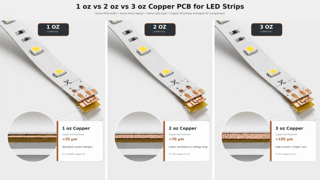
| 1 oz | 35 µm | 100% | Lowest cost and good flexibility | Higher voltage drop at the same current and geometry | Short, low-power or frequently fed installations |
| 2 oz | 70 µm | 50% | Strong balance of voltage-drop control and manufacturability | Higher cost and stiffness than 1 oz | Professional 24V strips, commercial lighting and moderate runs |
| 3 oz | 105 µm | 33% | Lower conductor loss in high-current layouts | Higher cost, greater stiffness and more difficult fabrication | Specialized high-current or space-constrained designs |
*Assuming the same copper type, trace width, length and temperature.
These figures describe conductor resistance—not guaranteed LED strip run length, current rating or operating temperature.
What Does “1 oz Copper” Actually Mean?
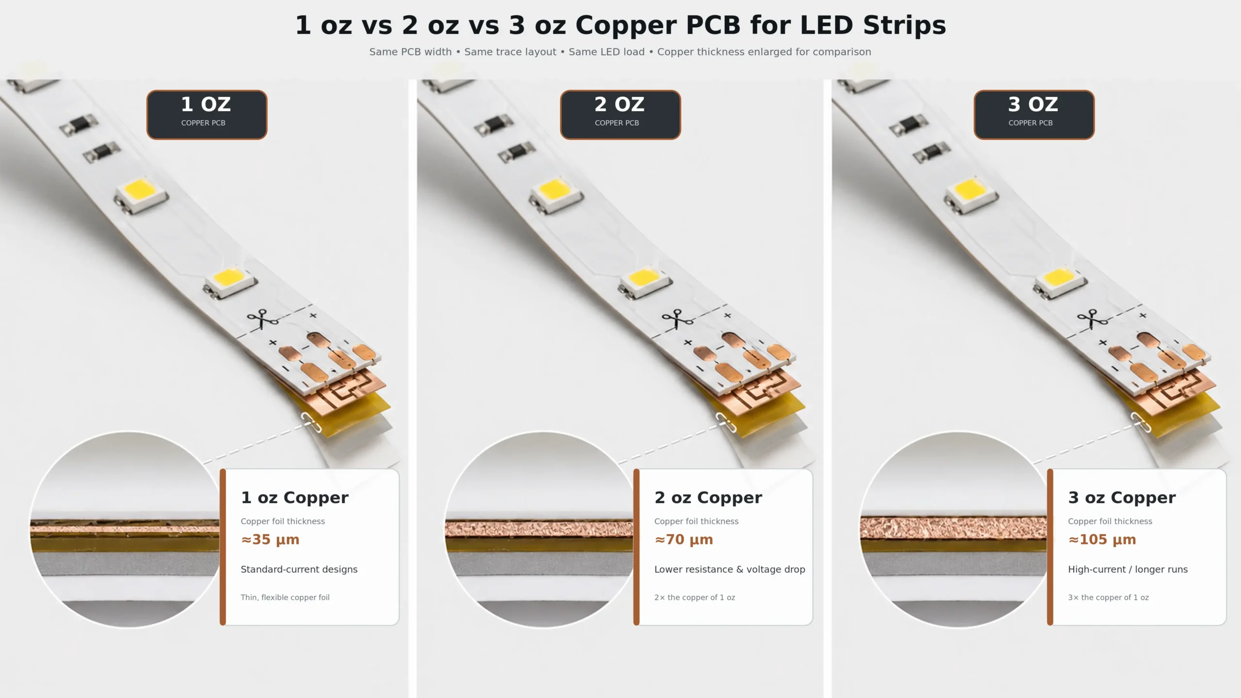
PCB copper weight is traditionally expressed in ounces per square foot. One ounce of copper distributed evenly over one square foot produces a nominal thickness of approximately 35 micrometers.
Therefore:
- 1 oz copper ≈ 35 µm
- 2 oz copper ≈ 70 µm
- 3 oz copper ≈ 105 µm
IPC defines copper weight as the mass of copper per unit area. It also distinguishes conductor thickness from non-conductive coatings such as solder mask or coverlay. The IPC-2152 standard explains that conductor size, current and acceptable temperature rise must be evaluated together.
DuPont’s flexible-circuit material data also identifies commonly available 35 µm and 70 µm copper constructions and distinguishes rolled-annealed copper from electrodeposited copper in its Pyralux flexible laminate data.
However, an LED strip specification that says “2 oz PCB” may still leave several questions unanswered:
- Is 2 oz the starting foil or the finished conductor thickness?
- What is the manufacturing tolerance?
- Is the copper rolled-annealed or electrodeposited?
- How wide are the actual positive and negative power rails?
- Are there narrow sections around cut marks and components?
- Is the PCB single-layer, double-layer or multilayer?
- Was copper thickness verified by cross-section inspection?
This is why copper weight should be treated as one design parameter, not a complete quality certificate.
Why Copper Thickness Changes Voltage Drop
The electrical resistance of a copper conductor can be approximated by:
R = ρL ÷ A
Where:
- R = conductor resistance
- ρ = copper resistivity
- L = conductor length
- A = conductor cross-sectional area
For a rectangular PCB trace:
A = trace width × copper thickness
This produces four straightforward relationships:
- Longer traces have more resistance.
- Narrower traces have more resistance.
- Thinner copper has more resistance.
- Warmer copper has more resistance.
The Copper Development Association gives a reference electrical resistivity of approximately 1.71 µΩ·cm for copper in its copper material data.
If the trace width and length remain unchanged, doubling the copper thickness approximately doubles the cross-sectional area and halves the resistance.
Therefore, in an ideal comparison:
- 2 oz has approximately 50% of the resistance of 1 oz.
- 3 oz has approximately 33% of the resistance of 1 oz.
- 3 oz has approximately 67% of the resistance of 2 oz.
But real LED strips are not ideal, uniform copper bars. Component pads, cutting points, vias, connectors and changes in rail width can introduce local bottlenecks.
The First Contrarian Finding: PCB Width Can Matter as Much as Copper Weight
A supplier may promote “2 oz copper” without showing how much of the PCB width is actually used for power distribution.
Consider two simplified power rails:
- 1 oz copper with a 4 mm-wide rail
- 2 oz copper with a 2 mm-wide rail
Their copper cross-sectional areas are approximately equal:
4 mm × 35 µm = 2 mm × 70 µm
Under the same conditions, their ideal conductor resistance will also be approximately equal.
This means a well-routed 10 mm-wide, 1 oz PCB could outperform a poorly routed 5 mm-wide, 2 oz PCB.
The overall strip width is not enough, either. A 10 mm PCB may contain only narrow power rails because LEDs, resistors, cut pads and signal traces occupy much of the available area.
When comparing samples, ask for:
- Total PCB width
- Effective positive rail width
- Effective negative or channel-return rail width
- Copper thickness
- Narrowest conductor section
- PCB layer count
- Measured start-to-end voltage
A copper-weight claim without trace geometry is only half a specification.
The Second Contrarian Finding: Higher Voltage Can Beat Thicker Copper
For a fixed amount of power:
Current = Power ÷ Voltage
A 48W LED strip load draws approximately:
- 4A at 12V
- 2A at 24V
- 1A at 48V
Voltage drop is:
Vdrop = I × R
Copper conductor heating is:
Ploss = I² × R
At the same power and conductor resistance:
- Changing from 12V to 24V halves the current.
- Copper loss falls to approximately one-quarter.
- Changing from 24V to 48V again halves the current.
- Copper loss again falls to approximately one-quarter.
Relative voltage drop is particularly important:
Voltage-drop percentage ≈ Power × Resistance ÷ Voltage²
That means system voltage has a squared relationship with percentage voltage drop at the same power.
For example, a 12V strip using 2 oz copper can still have approximately twice the percentage voltage drop of a comparable 24V strip using 1 oz copper.
This does not make 48V correct for every project. Higher-voltage strips can involve longer cutting units, different controllers and fewer compatible accessories. But it explains why copper weight should never be evaluated independently of voltage.
For long architectural runs, compare thicker copper with alternative system designs such as 36V and 48V long-run LED strips and planned power injection before specifying 3 oz copper by default.
LED Strip Loads Are Distributed, Not Located Only at the Far End
A common voltage-drop calculation assumes that the entire load is connected at the far end of the strip.
That is not how most LED strips operate.
LEDs and resistors are distributed along the PCB. Each circuit section draws some current, so the copper rails carry the highest current near the power input. Current gradually decreases as it travels toward the far end.
Consequently, a conventional cable calculation that places the full strip current at the far end usually overestimates PCB voltage drop.
For a simplified uniform distributed load, the far-end voltage drop may be approximately half the result of a full-current, end-loaded model. Actual behavior will differ because:
- LED current changes with voltage and temperature.
- Constant-current IC strips regulate current differently.
- RGB and RGBW channels do not always operate at equal loads.
- PCB power rails may change width.
- Connectors and input wires add resistance.
- Copper resistance increases as the strip becomes warmer.
A proper LED strip voltage-drop model should therefore use either distributed-load calculations or measured electrical data from the actual strip.
A Transparent Voltage-Drop Example
Consider a hypothetical 5-meter, 24V LED strip rated at 9.6W/m:
- Total rated power: 48W
- Nominal input current: 2A
- Copper rail width: 3 mm per conductor
- Uniformly distributed load
- Copper temperature initially assumed near 20°C
- No connector or input-wire resistance included
The estimated results are:
| Copper weight | Approximate far-end drop | Drop percentage | Estimated distributed PCB loss |
| 1 oz | 1.64V | 6.8% | 2.19W |
| 2 oz | 0.82V | 3.4% | 1.10W |
| 3 oz | 0.55V | 2.3% | 0.73W |
This model demonstrates the relative benefit of thicker copper. It is not a universal product rating.
If the actual rails are wider, the voltage drop will be lower. If the PCB is hotter, narrower or connected through resistive joints, it will be higher. The strip may also draw less than its rated power as the voltage falls, which changes the result.
The correct way to approve a product is to measure it at its rated run length after thermal stabilization.
Does Thicker Copper Improve Heat Dissipation?
Yes—but not in the way many product descriptions suggest.
Thicker copper can help in two different ways.
1. It Reduces Conductor Heat
PCB power-distribution loss follows:
Ploss = I²R
Reducing resistance reduces the heat generated inside the copper rails. This is especially valuable near the power-input end, where current is highest.
2. It Spreads Heat Along the PCB
Copper has high thermal conductivity. More copper can spread heat laterally and reduce sharp local temperature gradients around LED pads, resistors and narrow conductors.
However, thicker copper does not make the electrical energy consumed by the LEDs disappear. Most of the LED input power still becomes heat, regardless of whether the PCB uses 1 oz or 3 oz copper.
For steady-state operating temperature, the complete thermal path matters:
LED junction → LED package → solder joint → copper pad → flexible substrate → adhesive tape → aluminum profile → surrounding air
A failure anywhere in that path can dominate the result.
Therefore:
- 3 oz copper on an insulated surface can run hotter than 1 oz copper bonded correctly to a suitable aluminum profile.
- A thick PCB cannot repair an air gap caused by poor adhesive contact.
- Waterproof silicone can trap heat even when the strip uses heavy copper.
- A high-efficiency LED strip may run cooler than a lower-efficiency strip with thicker copper because less input power is converted to heat for the same light output.
For thermally demanding installations, copper construction should be evaluated together with LED efficacy, W/m, profile mass and mounting conditions. Xmart’s high-efficiency LED strip range is designed around this system-level relationship rather than copper thickness alone.
Why 3 oz Copper Does Not Give Three Times the Run Length
If 3 oz copper has approximately one-third the resistance of 1 oz copper, it may appear logical to assume that it provides three times the usable run length.
That conclusion is usually wrong.
Maximum run length is limited by more than PCB resistance:
- Minimum acceptable voltage at the far end
- Brightness variation from start to end
- Color shift
- Maximum connector and solder-joint current
- Input-pad temperature
- Controller output rating
- Power-supply capacity
- Cable voltage drop
- PCB temperature
- Cut-unit circuit design
- Constant-voltage or constant-current architecture
Resistance also increases with length, while total strip current usually increases as more meters are added. Under a simplified distributed load, voltage drop grows approximately with the square of length.
As a result, cutting resistance to one-third does not automatically triple the allowable length.
The final run length must be validated as a complete system.
Multi-Channel LED Strips Need Special Attention
Copper distribution becomes more complicated in RGB, RGBW, tunable-white and RGBCCT strips.
In a common-positive RGBW strip:
- The positive rail carries the combined current of all active channels.
- Each R, G, B or W return rail carries its individual channel current.
- The highest current may occur when multiple channels operate simultaneously.
- Controller firmware may limit the combined output below the sum of individual channel ratings.
A supplier may test an RGBW strip using one channel at full brightness. The same strip could experience a very different voltage drop when RGB and white channels operate together.
For multi-channel products, request test data for realistic worst-case operating modes, such as:
- Full white produced by RGB
- Dedicated white channel at full output
- RGB plus white simultaneously
- Both tunable-white channels active, if permitted
- The controller’s actual maximum combined output
The shared power rail, controller, connector and input cable must all withstand the combined current.
1 oz Copper: When It Is the Correct Choice
A 1 oz flexible PCB can be entirely appropriate when the electrical and mechanical design supports it.
Typical suitable conditions include:
- Short sections
- Low W/m
- 24V instead of 12V
- Frequent parallel feeds
- Furniture and cabinet lighting
- Small luminaires with limited bending stress
- Cost-sensitive products with controlled installation conditions
- Applications where flexibility is more important than maximum run length
A professional design does not use thicker copper than necessary. It uses enough copper to meet the voltage-drop, temperature and reliability requirements with an appropriate safety margin.
The risk appears when a 1 oz PCB is combined with high power, narrow rails and a long single-end feed.
2 oz Copper: The Practical Professional Balance
For many commercial 24V LED strips, 2 oz copper provides a strong compromise.
Potential benefits include:
- Lower voltage drop than an equivalent 1 oz design
- Lower PCB conductor loss
- Better current distribution
- Improved tolerance of moderate run lengths
- Better support for higher-power white and multi-channel strips
- Less stiffness and manufacturing difficulty than many 3 oz designs
It is often suitable for:
- Architectural cove lighting
- Retail and hospitality projects
- Medium- and high-output LED strips
- Five-meter reels with controlled brightness uniformity
- RGBW and tunable-white systems
- Strips where power injection is possible but should be minimized
However, “2 oz” should still be supported by actual run-length, voltage and temperature data.
3 oz Copper: When the Extra Copper Is Justified
Three-ounce copper is most useful when the project has a genuine conductor-resistance problem that cannot be solved more efficiently by changing voltage, width or feed topology.
Possible applications include:
- High-current LED strips
- High-output multi-channel strips
- Narrow PCBs with limited rail width
- Installations where intermediate power injection is inaccessible
- Custom luminaires with strict end-to-end uniformity requirements
- Specialized products with verified input-pad and connector capacity
But 3 oz copper introduces trade-offs:
- Higher material cost
- More difficult etching of fine features
- Potentially larger minimum spacing requirements
- Reduced flexibility
- Greater stress at repeated bending points
- Higher thermal mass during soldering
- Possible compatibility problems with solderless connectors
- More limited manufacturing availability
- Higher minimum order quantities or longer lead times
Three-ounce copper should be an engineering decision, not a premium label added to a datasheet.
Copper Type Matters Too: RA vs ED Copper
Copper weight does not describe how the foil was manufactured.
Flexible PCBs may use:
- Rolled-annealed copper, or RA copper
- Electrodeposited copper, or ED copper
The copper type, grain structure, laminate system and circuit construction can affect bending performance. DuPont, for example, distinguishes RA and ED foil versions in its flexible laminate product codes.
For an LED strip installed once in a straight aluminum profile, dynamic flex endurance may not be the primary requirement. For strips used in moving assemblies, curved products or repeated bending, it becomes much more important.
Do not assume that a heavier copper weight automatically provides better mechanical reliability. A thick conductor may carry current well while being less suitable for repeated flexing.
Flexible PCB design and performance requirements can be specified through standards such as IPC-2223 and IPC-6013, depending on the product and acceptance level.
Copper Weight vs Total Project Cost
The cheapest LED strip is not necessarily the one with the lowest price per meter.
The relevant calculation is installed system cost:
Total project cost = strip + drivers + cables + connectors + control equipment + profiles + installation labor + maintenance
A 2 oz strip may cost more per meter than a 1 oz strip but reduce the need for:
- Additional power-injection cables
- Junction boxes
- Driver locations
- On-site soldering
- Installation labor
- Troubleshooting visits
In that case, the more expensive PCB may produce a lower installed cost.
However, moving from 2 oz to 3 oz may provide a smaller financial return if the project can be improved more efficiently by:
- Center feeding
- Feeding from both ends
- Using parallel branches
- Increasing system voltage
- Reducing W/m
- Selecting more efficient LEDs
- Increasing PCB or power-rail width
The best solution is the one that achieves the required uniformity and temperature at the lowest complete-system cost—not necessarily the strip with the most copper.
Power Injection Can Be More Effective Than Adding Copper
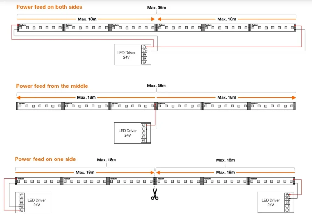
Power-injection strategy changes how much current each section of the PCB must carry.
One-End Feed
This is the simplest arrangement, but the input section carries the current for the entire strip. It usually produces the greatest far-end voltage drop.
Feed from Both Ends
Current enters from both ends and travels toward the center. This shortens the maximum current path and can improve voltage uniformity.
Both feeds must use the same voltage reference and correct polarity. The power supply, wiring and protection method must be designed for the complete load.
Center Feed
The strip is divided electrically into two shorter branches. Current travels outward in both directions, which can significantly reduce the maximum path length.
Parallel Branches
Multiple strips are connected separately to a distribution point instead of being daisy-chained. This often gives better results than specifying extremely heavy copper for one long continuous run.
Use an engineering calculation before deciding which arrangement is best. Xmart’s LED strip voltage-drop and power-injection guide can help compare voltage, run length, power and feed position.
Do Not Ignore the Connector Bottleneck
The PCB may use 3 oz copper while the solderless connector contains a thin contact with a small contact area.
That connector can become the highest-resistance part of the circuit.
Common bottlenecks include:
- Small connector contacts
- Oxidized contact surfaces
- Insufficient clamping force
- Repeatedly reused connectors
- Narrow wire-to-board terminals
- Small solder pads
- Incomplete solder wetting
- Undersized lead wires
- Shared controller terminals carrying several channels
A complete current path should be evaluated from the power-supply terminal to the final LED segment.
Copper thickness cannot protect a connector that is operating beyond its rating.
How to Compare LED Strip Samples Properly
Copper thickness is difficult to verify visually. A meaningful sample evaluation should combine construction evidence with electrical and thermal testing.
Request These Specifications
Ask the manufacturer for:
- Nominal and minimum finished copper thickness
- Copper type: RA or ED
- PCB layer count
- Overall PCB width
- Effective power-rail width
- Rated W/m
- Measured input power at the specified length
- Maximum recommended run per feed
- Maximum operating current
- Connector and lead-wire ratings
- Recommended profile and mounting method
- Test ambient temperature
- Start, middle and end voltage
- Start, middle and end illuminance or luminous output
- Stabilized PCB temperature
Test the Complete Rated Length
Do not approve a long-run product after testing only one meter.
Install the manufacturer’s maximum recommended run and use:
- The specified power supply
- The specified feed-wire size and length
- The intended aluminum profile
- The intended waterproof construction
- The intended dimming or control method
Allow the Strip to Stabilize
Voltage drop and temperature should not be recorded immediately after power-on. Copper resistance, LED voltage and input power change as the strip warms.
Record results after the system reaches a reasonably stable operating temperature.
Measure at Several Locations
Measure:
- Supply voltage at the driver
- Voltage at the strip input
- Voltage at the midpoint
- Voltage at the far end
- Input current
- Surface temperature near the input
- Surface temperature near the middle
- Brightness and color at multiple positions
A strip can have acceptable far-end voltage but unacceptable input-pad temperature. It can also maintain brightness while shifting color.
Verify Production, Not Only the Golden Sample
For significant OEM orders, define production acceptance criteria such as:
- Minimum finished copper thickness
- Maximum resistance per meter
- Maximum voltage difference
- Maximum brightness variation
- Maximum stabilized temperature
- Approved PCB material and copper type
- Approved component and connector construction
Cross-section inspection or resistance testing can be used when copper thickness is contractually important.
A Better LED Strip PCB Specification
Instead of writing only:
2 oz copper PCB
Use a performance-based specification such as:
24V constant-voltage LED strip, 9.6W/m nominal, 10 mm flexible PCB, minimum finished copper thickness of 70 µm, maximum five-meter single-end feed, maximum 3% measured strip voltage drop at stabilized temperature, installed in the approved aluminum profile at 25°C ambient.
This specification is much harder to manipulate because it combines construction with an observable result.
Depending on the project, also add:
- Maximum brightness variation from first to last segment
- Maximum CCT or chromaticity shift
- Maximum PCB temperature at the input
- Test power-supply voltage
- Feed-wire gauge and length
- Aluminum profile model
- Waterproof construction
- Dimming state
- Measurement tolerance
Selection Guide
| Project condition | Starting recommendation | What to verify |
| Short, low-power, dry indoor sections | 1 oz may be sufficient | Far-end voltage and temperature |
| Standard professional 24V installation | Compare well-designed 1 oz and 2 oz products | Rail width, measured run length and profile |
| Moderate or high W/m | 2 oz is often a practical starting point | Input temperature and brightness uniformity |
| RGBW or RGBCCT strip | 2 oz or application-specific design | Combined-channel current and common-rail width |
| Ultra-narrow PCB | Do not select by copper weight alone | Actual rail cross-section and aluminum profile |
| Long single-end run | Consider higher voltage or regulated strip | Voltage-drop test across full length |
| Repeated bending or moving application | Review copper type and flex construction | Bend radius and cycle testing |
| High-current specialized strip | 3 oz may be justified | Connector, solder pad, flexibility and manufacturing tolerance |
| Difficult-to-access installation | Optimize complete system before installation | Feed topology, maintenance and TCO |
Questions to Ask an LED Strip Manufacturer
Before approving a product, ask:
- Is the advertised copper weight the base foil or finished conductor thickness?
- What is the minimum finished thickness after production?
- What are the effective widths of the positive and negative power rails?
- Is the copper rolled-annealed or electrodeposited?
- What is the maximum tested run length from one feed?
- At what voltage, W/m and ambient temperature was it tested?
- What are the start and far-end voltages?
- How much does brightness change across the tested length?
- Was the test performed inside the recommended aluminum profile?
- What connector and cable sizes were used?
- What happens when all color channels operate simultaneously?
- Can production batches be accepted by resistance or cross-section testing?
A technically capable supplier should be able to explain the electrical result—not simply repeat the copper weight.
Frequently Asked Questions
Is 2 oz copper always better than 1 oz for LED strips?
Not always. For the same trace layout, 2 oz copper offers lower resistance. However, a wider 1 oz rail, higher system voltage or better feed topology may outperform a poorly designed 2 oz strip.
Does 2 oz copper carry twice the current?
Not automatically. Current-carrying capability depends on conductor width, thickness, temperature rise, surrounding materials, installation and acceptable reliability limits. IPC-2152 evaluates conductor size and temperature together rather than assigning one universal amp rating to a copper weight.
Does 3 oz copper make an LED strip run three times longer?
No. Maximum run length also depends on voltage, W/m, circuit design, power injection, connectors, cables and acceptable brightness variation. Voltage drop can grow rapidly as both length and total load increase.
Does thicker copper make LEDs cooler?
It reduces heat generated by PCB resistance and can improve heat spreading. It does not eliminate the heat produced inside the LEDs. The aluminum profile, thermal interface, LED efficacy, waterproofing and ambient temperature remain critical.
Can a 1 oz LED strip still be high quality?
Yes. A short, efficient 24V strip with wide rails and correct thermal management can perform reliably with 1 oz copper. Quality should be judged by measured electrical, optical, thermal and reliability performance.
Is 3 oz copper better for flexible or curved installations?
Not necessarily. Thicker copper usually makes the PCB less flexible. Copper type, laminate construction, bend radius and number of bending cycles must also be considered.
How can I verify the copper thickness?
For formal verification, use PCB cross-section measurement or qualified material documentation. Resistance-per-meter testing can also identify significant inconsistencies, although it is influenced by rail width, copper type and measurement temperature.
Should I choose thicker copper or a higher-voltage LED strip?
If long-run voltage drop is the main problem, increasing the system voltage can sometimes provide a larger improvement than increasing copper thickness. The final decision should also consider cutting length, dimming compatibility, electrical safety and component availability.
Final Recommendation
Copper weight matters—but it is not an independent measure of LED strip quality.
The best PCB is not automatically the one with the thickest copper. It is the one whose copper thickness, rail width, voltage, W/m, circuit architecture and feed method work together to meet the project’s requirements.
Use these principles:
- Choose 1 oz when the load and run length genuinely allow it.
- Use 2 oz when it provides a worthwhile balance of voltage-drop control, flexibility and cost.
- Specify 3 oz only when testing or calculation demonstrates a real benefit.
- Compare copper cross-sectional area, not copper weight alone.
- Evaluate system voltage before paying for heavier copper.
- Test the complete rated run after thermal stabilization.
- Measure voltage, brightness, color and temperature—not just watts.
- Include cables, connectors and power injection in the analysis.
As a custom LED strip manufacturer, Xmart Lighting can evaluate PCB width, copper construction, operating voltage, wattage, LED efficiency, feed topology and aluminum-profile requirements as one system. For OEM, distributor and project orders, this makes it possible to select the copper construction based on measurable performance rather than an isolated marketing claim.

When requesting a quotation or sample, provide the required run length, voltage, W/m, profile dimensions, feed locations and maximum acceptable brightness variation. Those details are more useful than asking for “the thickest PCB available.”