A 0–10V dimmable LED flat panel does not automatically turn completely off when the control signal reaches 0V.
Some drivers dim only to a minimum light level. Some support electronic dim-to-off. Others require a relay or switch to disconnect line voltage.
The final behavior depends on the complete combination of:
- LED driver
- 0–10V controller
- Relay or power pack
- Control wiring
- Line-voltage supply
- Minimum dimming settings
- Selected wattage
- Control-system programming
For distributors, contractors and project buyers, “0–10V dimmable” should begin a compatibility review—not end it.
Quick Answer
A standard 0–10V label does not independently guarantee:
- Dim-to-off operation
- 1% or 10% minimum light output
- Flicker-free low-end dimming
- Smooth dimming
- Identical dimming between panels
- A specific dimming curve
- Compatibility with every controller
- The number of panels allowed on one control circuit
- The state of the fixture after control-signal failure
To guarantee dim-to-off, both the driver and controller must support compatible electronic-off behavior, or the control system must switch off the panel’s line-voltage supply.
What Does 0–10V Dimming Actually Mean?
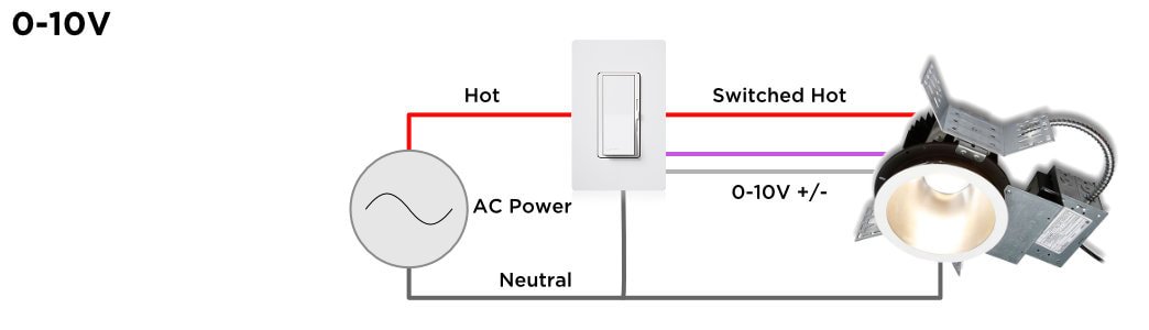
0–10V is an analog control method in which a low-voltage control signal tells the LED driver what output level to produce.
The LED panel still receives its normal line-voltage input, such as 120V or 277V. The 0–10V wires carry a control signal; they do not provide the main operating power for the luminaire.
In a common commercial arrangement:
- A higher control voltage requests higher output.
- A lower control voltage requests lower output.
- The driver converts that signal into LED output current.
- A separate switch or relay may interrupt line voltage for complete shutoff.
ANSI C137.1-2022 defines interface and performance requirements for 0–10V controls and drivers where output is adjustable between minimum or off and maximum.
However, not every product marketed as 0–10V dimmable is necessarily specified for electronic off under ANSI C137.1.
Why 0V Does Not Always Mean Off
Legacy and current 0–10V systems do not all interpret the low end in the same way.
Depending on the driver:
- 10V may represent maximum output.
- 1V may represent the driver’s minimum output.
- 0V may maintain that minimum output.
- A signal below a defined threshold may trigger electronic off.
- Complete off may require line voltage to be switched.
This is why one panel may turn off at the bottom of a dimmer’s travel while another remains faintly illuminated.
The driver specification should identify:
- Minimum control voltage
- Minimum light output
- Turn-off threshold
- Turn-on threshold
- Whether electronic off is supported
- Whether switched line voltage is required
A generic “0–10V dimmable” line on a specification sheet does not answer these questions.
Three Common 0–10V System Behaviors
| System Behavior | Low-End Result | How Complete Off Is Achieved |
|---|---|---|
| Minimum-output dimming | Panel remains on at minimum level | Separate line-voltage switch or relay |
| Electronic dim-to-off | Driver enters standby below a defined control voltage | Compatible driver and controller |
| Dimming plus relay | Control signal reduces output; relay disconnects power | Relay or power pack opens line voltage |
None of these architectures is automatically wrong. The correct choice depends on the project’s control sequence, energy code, emergency operation and user expectations.
The problem occurs when the supplier, controls contractor and buyer assume different behaviors.
Dim-to-Off Requires Both Sides to Agree
A dim-to-off driver cannot guarantee dim-to-off if the controller cannot send the required low-end signal.
Likewise, a controller that supports electronic off cannot turn off a driver that only dims to its minimum output.
Lutron’s 0–10V topology guidance states that both the control and driver must support the relevant electronic-off behavior. If compatibility is not stated, switching line voltage is the more reliable way to ensure the lights turn off.
A complete submittal should therefore identify:
- LED driver manufacturer and model
- 0–10V control manufacturer and model
- Sink or source behavior
- Electronic-off compatibility
- Minimum dimming level
- Relay requirement
- Maximum driver quantity per control
- Tested or recommended control combinations
“Dims to 10%” Is Also Incomplete
A minimum dimming claim should explain what the percentage represents.
It may refer to:
- Measured light output
- LED output current
- Driver power
- Control voltage
- Perceived brightness
These values are not interchangeable.
For example, a driver operating at 10% output current may not produce exactly 10% measured lumens. Human vision also does not perceive changes in brightness linearly.
Buyers should request the minimum measured light output of the finished LED panel when used with the specified control.
Linear and Logarithmic Dimming Can Feel Different
Two systems can reach the same minimum and maximum levels while appearing different during dimming.
A linear electrical response does not necessarily create a visually linear change. A large portion of the visible brightness change may appear near one end of the control range.
The result can depend on whether the driver and control use:
- Linear response
- Logarithmic response
- A programmed dimming curve
- Low-end trim
- High-end trim
This explains why one panel appears to dim smoothly while another seems to change very little at first and then drop rapidly near the bottom.
The specification should state both the minimum level and expected dimming behavior.
Why LED Panels Flicker at the Low End
A panel may operate normally at full output but flicker, pulse or switch off unexpectedly near its minimum level.
Possible causes include:
- Driver and controller incompatibility
- Control-signal noise
- Excessive voltage drop on the control wires
- Reversed 0–10V polarity
- Driver operating below its stable output range
- Incorrect low-end trim
- Too many drivers on one control circuit
- Different driver revisions within one project
- Poor connection or insulation
- Emergency or sensor equipment interfering with the signal
A low-end failure is not always caused by the LED board. It may be a system-level interaction between the controller, driver and wiring.
For performance-sensitive projects, test the actual panel and actual controller together before approving bulk production.
One 0–10V Control Cannot Be Sized by Fixture Watts Alone
The number of panels connected to a control zone may be limited by several independent factors:
- Line-voltage relay capacity
- LED-driver inrush current
- 0–10V source or sink current
- Control-wire voltage drop
- Manufacturer’s maximum device count
- Emergency-control requirements
The low wattage of LED panels can make the 0–10V milliamp rating the limiting factor before the relay’s wattage or amp rating is reached.
A simplified control-current calculation is:
Maximum theoretical drivers = controller sink capacity ÷ source current per driver
For example, a 60mA control paired with drivers that each source 2mA gives a theoretical limit of 30 drivers.
That is not automatically the permitted project quantity. Relay rating, inrush current, wire length, safety factor and manufacturer instructions may reduce the final number.
Sink and Source Compatibility Matters
A 0–10V circuit needs one side to provide the small control current and the other side to absorb it.
In many commercial systems based on IEC 60929-style behavior:
- The driver sources the control current.
- The control device sinks it.
Other architectures exist. Connecting two devices that expect the same role can produce incorrect or unstable operation.
The correct specification should identify whether the control and driver are:
- Current sinking
- Current sourcing
- Automatically detecting sink/source behavior
The labels “0–10V” or “1–10V” are not sufficient when device roles are unclear.
Open Control Wires Do Not Necessarily Mean Off
In many current-sinking commercial systems, opening the control circuit causes the driver to return to high output because the driver sees a high control voltage.
Shorting or pulling the control signal low may reduce the output to its minimum or electronic-off state.
This behavior is useful as a fail-safe in some applications, but it can surprise installers who assume that disconnecting the dimming wires will switch off the luminaire.
Actual behavior must be verified from the driver and control documentation.
Electrical work should be performed by qualified personnel in accordance with the product instructions and applicable local code.
DLC “Dimmable” Does Not Prove Dim-to-Off
The current DLC SSL V6.0 technical requirements require reporting of details including driver type, dimming capability and minimum dimming level.
For many indoor luminaires, continuous dimming to 20% output or lower can satisfy the standard dimming requirement.
DLC also states that listed control capabilities are based on manufacturer claims and that dimming performance is not independently verified by DLC.
Therefore, a DLC-qualified LED panel described as dimmable does not automatically prove:
- Dim-to-off
- 1% minimum output
- Compatibility with a particular wall control
- Smooth low-end performance
- Absence of flicker
- Maximum panel quantity per control zone
These details must still be confirmed at the model and driver level.
Selectable-Wattage Panels Need Compatibility Testing
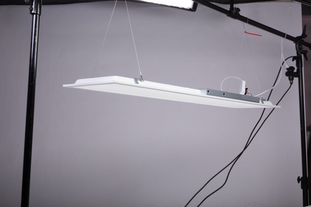
A selectable LED flat panel can operate at several wattage and lumen settings.
The 0–10V interface may remain the same, but changing the selected wattage can affect:
- Maximum lumen output
- Absolute minimum lumen output
- Driver operating point
- Low-end stability
- Inrush behavior
- Thermal conditions
A 10% minimum on a 30W setting produces a different absolute light level from 10% on a 72W setting.
For a field-adjustable panel, test at least the relevant driver configurations and the highest and lowest intended wattage settings.
A qualified LED flat panel light manufacturer should specify both the available wattage settings and the driver-level dimming behavior.
How to Evaluate an LED Panel and Controller Combination
Use an actual mock-up before approving a large order.
Test 1: Full Output
Confirm that the panel reaches stable full output without flicker, noise or unexpected variation.
Test 2: Smooth Dimming
Move gradually through the complete control range and observe:
- Sudden steps
- Dead travel
- Uneven changes
- Visible flicker
- Audible driver noise
Test 3: Minimum Level
Record the lowest stable output before flicker, dropout or color instability appears.
Test 4: Complete Off
Confirm whether the panel:
- Remains faintly on
- Enters electronic standby
- Requires a relay
- Turns back on unexpectedly
Test 5: Turn-On Behavior
Check for:
- Delayed start
- Pop-on at a higher level
- Different start levels between panels
- Failure to restart from the lowest setting
Test 6: Multiple Panels
Repeat the test using the expected number of panels on one control zone. A single-panel sample cannot reveal every current-capacity or wiring problem.
Test 7: Input Voltage
If the project uses both 120V and 277V systems, confirm operation under the relevant line-voltage condition.
Test 8: Selectable Settings
Test the intended wattage settings and relevant CCT configurations rather than assuming that one switch position represents all combinations.
Common Symptoms and What to Check
| Symptom | Possible Cause | What to Verify |
| Panel remains on at minimum | Driver does not support electronic off | Driver specification and relay requirement |
| Panel will not dim | Wrong control type, polarity or wiring | Sink/source behavior and control connections |
| Low-end flicker | Driver/control incompatibility or noise | Tested control list and live mock-up |
| Some panels turn off before others | Driver tolerance or voltage drop | Control current, wire run and low-end trim |
| Panel jumps on at 10–20% | Driver pop-on threshold | Turn-on specification and programming |
| Dimming is uneven | Different driver revisions or curves | Driver model and production change control |
| Control becomes unstable with many panels | Milliamp or inrush limit exceeded | Driver count, source current and relay rating |
| Lights return to full output after signal loss | Open-circuit fail-safe behavior | Driver control-input specification |
What B2B Buyers Should Put in the Specification
A useful 0–10V LED panel specification should include:
- Exact driver manufacturer and model
- Control-interface standard
- Current sink/source behavior
- Minimum measured light output
- Dim-to-off: yes or no
- Electronic-off standard or threshold
- Turn-on threshold
- Relay requirement
- Dimming curve
- Control current per driver
- Maximum recommended drivers per control
- Inrush-current information
- Compatible control list
- Control-wire classification
- Dimming-wire identification
- Low-end flicker acceptance
- Behavior after control-signal loss
- Behavior at each selectable wattage
- Component change-control policy
“0–10V dimmable” should be the summary—not the complete specification.
Manufacturer Verification Questions
Before placing an order, ask:
- What exact driver is installed?
- Does the driver support ANSI C137.1 electronic off?
- Does 0V mean minimum output or off?
- What is the lowest stable measured lumen output?
- Is a separate relay required?
- Is the driver current sourcing or sinking?
- How much control current does each driver use?
- How many panels can one control zone support?
- Which controllers have been tested?
- Is the dimming curve linear or logarithmic?
- Does the panel flicker or drop out at low end?
- What happens if the control wires are opened?
- Are the highest and lowest selectable wattages tested?
- Can the driver be changed without buyer approval?
- Is the dimming information included in the product report and specification sheet?
Buyers can review Xmart’s available commercial panel specifications and certification information before requesting model-level driver data.
Frequently Asked Questions
Does every 0–10V LED panel turn off at 0V?
No. Some drivers remain at their minimum output. Electronic dim-to-off must be supported by the driver and control, or line voltage must be switched.
Is 0–10V the same as 1–10V?
The terms are sometimes used inconsistently. Some systems define 1V as minimum light and require separate switching for off. Buyers should verify the driver’s actual control behavior rather than relying on the label.
Can a 0–10V panel be used without a dimmer?
Many drivers operate at full output when the dimming circuit is open, but this behavior must be verified from the driver instructions.
Does DLC qualification guarantee dim-to-off?
No. DLC dimming requirements and reported control capabilities do not automatically establish electronic-off behavior or compatibility with a specific controller.
Why do some panels flicker only when dimmed?
The driver may become unstable at low output, or the control signal may be affected by incompatibility, noise, wiring or control-current limitations.
How many panels can one 0–10V dimmer control?
It depends on the controller’s relay rating, 0–10V milliamp capacity, driver source current, inrush current, wiring and manufacturer limits.
Does 120–277V describe the dimming signal?
No. It describes the panel’s line-voltage input range. The 0–10V signal is a separate low-voltage control circuit.
Can changing the driver change dimming performance?
Yes. A different driver may have a different minimum output, dimming curve, current requirement, turn-on threshold and dim-to-off behavior.
Final Takeaway
A 0–10V label confirms that the panel has an analog dimming interface. It does not fully define how the installed system will behave.
A reliable commercial specification must connect:
LED panel → exact driver → exact controller → control current → minimum level → electronic off or relay → tested project quantity
For distributors, contractors and private-label brands, the safest approach is to test the actual driver and control combination before approving the complete order.
To review a commercial panel program, send Xmart the panel size, selectable wattages, project voltage, controller model, required minimum output, dim-to-off requirement and estimated fixture quantity through the commercial lighting quotation form.