
Tunnel LED Strip Lighting: Long-Run Design & Voltage Drop Guide
Design long-run tunnel LED strip lighting with the right voltage, load calculation, feed layout, cable size and validation method. Avoid far-end dimming before installation.
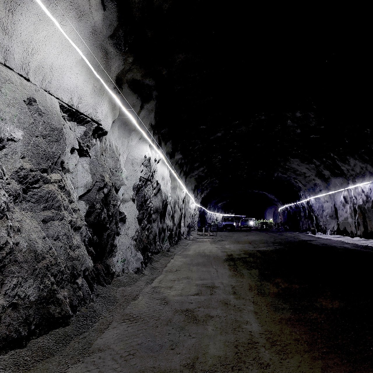
Tunnel LED Strip Lighting: How to Design Long Runs Without Voltage Drop
A tunnel LED strip can look uniform at the first power point and still become visibly weaker further down the route.
The cause is rarely one number on a product datasheet. Long-run performance depends on the relationship between strip load, supply voltage, feeder cable, power-feed position, connector losses and the resistance built into the strip itself.
The most reliable tunnel lighting layouts are designed from the route and electrical load first — not from reel length.
Direct Answer To reduce visible voltage-drop problems on long tunnel LED strip runs, calculate the total load, choose a suitable voltage, plan power-feed positions, size feeder cables correctly and validate the selected strip model under the intended conditions. Do not rely on a universal “maximum run length.”
The Question Is Not “How Many Metres Can It Run?”
The better question is: “At this load, with this voltage, this cable size and this feed layout, how consistent will the light remain along the route?”
A quoted “maximum run length” on a marketing sheet is often tested under ideal laboratory conditions. It assumes a specific power feed method and ignores the resistance of the long feeder cables required in real tunnel environments.
When this single number is detached from wattage, voltage, cable length, feed direction, and actual installation conditions, it becomes a severe risk to project handover.
Engineering Rule
A run-length figure is only useful when the strip model, watts per metre, supply voltage, power-feed method, cable size and test condition are known.
For Xmart’s available industrial strip configurations, visit the Tunnel & Mining LED Strip page.
There Are Two Different Voltage-Drop Problems
Understanding the difference is critical for accurate tunnel lighting design.
1. Feeder-Cable Voltage Drop
This occurs between the power supply and the first strip connection. The longer and thinner the feed cable, the more voltage is lost before power even reaches the LED strip.
Vdrop = 2 × L × I × R
This simple formula is useful for a conventional DC feeder cable. “2 × L” represents the round-trip path: outbound conductor plus return conductor.
2. LED Strip Conductor Voltage Drop
This occurs along the strip itself. Unlike a single load at the end of a cable, LEDs are distributed along the strip. Current is drawn progressively across the route, and the strip’s copper conductors have their own resistance.
Critical Note: A simple feeder-cable formula alone cannot accurately confirm the far-end performance of a distributed LED strip load. Use model-specific Xmart data, measured test results or verified maximum-run guidance for the selected product.
Conceptual diagram: Separation of feeder losses and distributed load losses.
Five Inputs Decide Whether the Route Will Stay Uniform
Total connected load
A 5W/m strip and a 10W/m strip may look similar in a product photo, but their current demand and power-feed requirements can be very different.
System voltage
For the same total wattage, a higher-voltage system operates at lower current. Lower current can reduce voltage-drop pressure in the feeder cable and system conductors.
Power-feed location
The same strip can perform differently when powered from one end, both ends, the centre or multiple planned zones.
Feeder-cable size and length
Cable resistance is affected by conductor size and cable length. Long undersized cables can create a major voltage loss before the strip begins.
Strip construction and actual environment
The strip’s conductor design, watts per metre, connection method, ambient temperature, vibration, moisture and installation method can all influence real-world performance.
Technical Warning
Do not calculate a long route from voltage alone. 48V can reduce current, but it does not compensate for an undersized cable, overloaded power supply, poor connector or incorrect feed layout.
Calculate the Load Before You Discuss Run Length
Before selecting a specific LED strip model, establish the baseline electrical requirements for your tunnel route.
Total Load = Length × Watts per Metre
Current = Total Load ÷ Voltage
Preliminary Supply Capacity = Total Load × (1 + Headroom Percentage)
Preliminary Tunnel LED Strip Load Estimator
Estimated Outputs (Preliminary)
Disclaimer: This tool is for preliminary load planning only. It does not calculate strip-conductor voltage drop, cable voltage drop, breaker selection, short-circuit protection, hazardous-area compliance or final electrical suitability. Confirm the final layout with the selected Xmart product data and a qualified electrical professional.
Four Long-Run Power-Feed Layouts
One-End Feed
Best for:
Shorter controlled sections within the verified operating range of the selected model.
Risk to watch:
The far end may receive lower voltage as the run and load increase.
Two-End Feed
Best for:
A route where power can be supplied from both ends to improve electrical balance.
Risk to watch:
Both feed paths must be designed correctly for polarity, protection and service access.
Centre Feed
Best for:
A route that can be divided into two balanced directions from a central power point.
Risk to watch:
The layout should be planned around actual route geometry and equal load distribution.
Segmented Feed Zones
Best for:
Extended tunnels, conveyors and infrastructure corridors where power can be introduced at planned intervals.
Risk to watch:
Each zone needs clear labelling, isolation, maintenance access and consistent documentation.
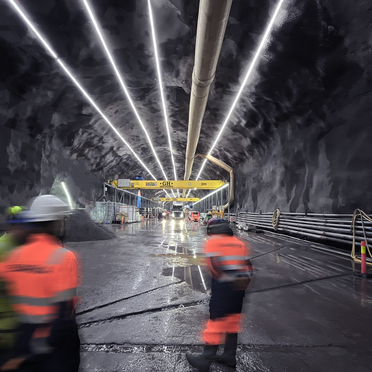
The layout with the fewest power supplies is not always the lowest-risk layout. The better design is the one that keeps output stable, remains serviceable and fits the available route infrastructure.
Do Not Confuse Supply Voltage with Regulation Method
“48V” and “constant current” are not competing answers to the same question.
| Supply Voltage | Regulation Method |
|---|---|
| Examples: 24V, 36V, 48V | Examples: Constant voltage or constant current LED systems |
| What it changes: System current, feed-cable voltage-drop pressure and practical route planning. | What it changes: How the LED circuit manages current and output across the strip. |
A constant-current product may support different long-run behaviour from a conventional constant-voltage strip, but it still has defined limits. Confirm the actual Xmart model and its installation guidance before final specification.
For related voltage-drop questions, see the Xmart LED Strip FAQ.
The Strip Is Only One Part of the Circuit
A high-quality strip can still perform poorly if the power supply, cable, connector or installation method is underspecified.
| Component | What to Check Before Approval |
|---|---|
| Power supply | Continuous-load suitability, required headroom, ambient temperature, enclosure and maintenance access. |
| Feeder cable | Conductor size, length, routing method, voltage loss and mechanical protection. |
| Connector | Voltage and current compatibility, sealing, strain relief, vibration resistance and replacement access. |
| Strip connection point | Polarity, mechanical support, ingress protection and route labelling. |
| Mounting method | Fixing interval, vibration exposure, access for replacement and protection from damage. |
| Feed-zone documentation | Strip model, wattage, voltage, power-supply model, cable size and connection location. |
Validate the Installed Route, Not Just the First Metre
Before handover, test the installed system under its intended operating condition. A visual check alone is not enough for a long route.
- Confirm the installed strip model and watts per metre.
- Record route length and feed-zone locations.
- Confirm power-supply model and input/output settings.
- Measure voltage at the power supply output.
- Measure voltage at the first strip connection.
- Measure voltage at the midpoint and far end of each planned zone.
- Check for visible brightness or colour inconsistency along the route.
- Inspect connectors, end caps, cable entries and mounting points.
- Photograph and label each feed zone for future maintenance.
- Record any site conditions that differ from the original design.
If the measured far-end result does not match the expected design, investigate the feed cable, connector, load, feed topology and strip model before replacing the product.
Seven Mistakes That Create Avoidable Voltage-Drop Problems
- Choosing the strip by reel length rather than watts per metre and route load.
- Treating 48V as a substitute for electrical design.
- Using a feeder-cable formula to predict a distributed LED strip load without model-specific data.
- Adding power injection only after the strip is already mounted.
- Ignoring losses in long feed cables and connectors.
- Selecting a power supply too close to its intended continuous load.
- Failing to record feed-zone locations for future maintenance.
For diagnosis after installation, read Xmart’s LED Strip Troubleshooting Guide.
Tunnel LED Strip Voltage Drop FAQs
How do I calculate power for a tunnel LED strip?
Can I calculate voltage drop using only the tunnel length?
Does 48V LED strip lighting remove voltage-drop problems?
Should I power a long tunnel LED strip from both ends?
What information should I send Xmart for a long-run tunnel-lighting review?
Send the Route Plan Before You Order the Strip
A long-run tunnel LED strip project should be reviewed as a complete electrical route, not as a reel-length order.
Send Xmart your route drawing, total length, selected brightness, available voltage, planned feed points and installation environment. We can help you identify a suitable Tunnel & Mining LED Strip configuration and prepare for a more accurate technical discussion.
Request a Long-Run Tunnel Lighting Review